
Dielectric Ceramic Composition

Inactive Publication Date: 2009-04-23
YOKOWO CO LTD
View PDF5 Cites 9 Cited by
  • Summary
  • Abstract
  • Description
  • Claims
  • Application Information

AI Technical Summary

Benefits of technology

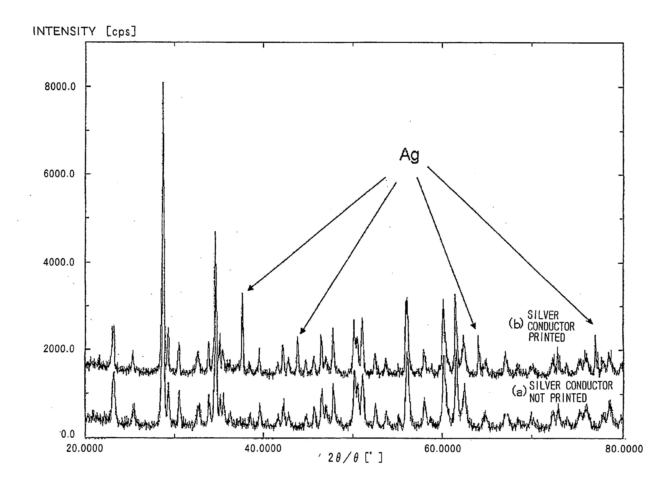
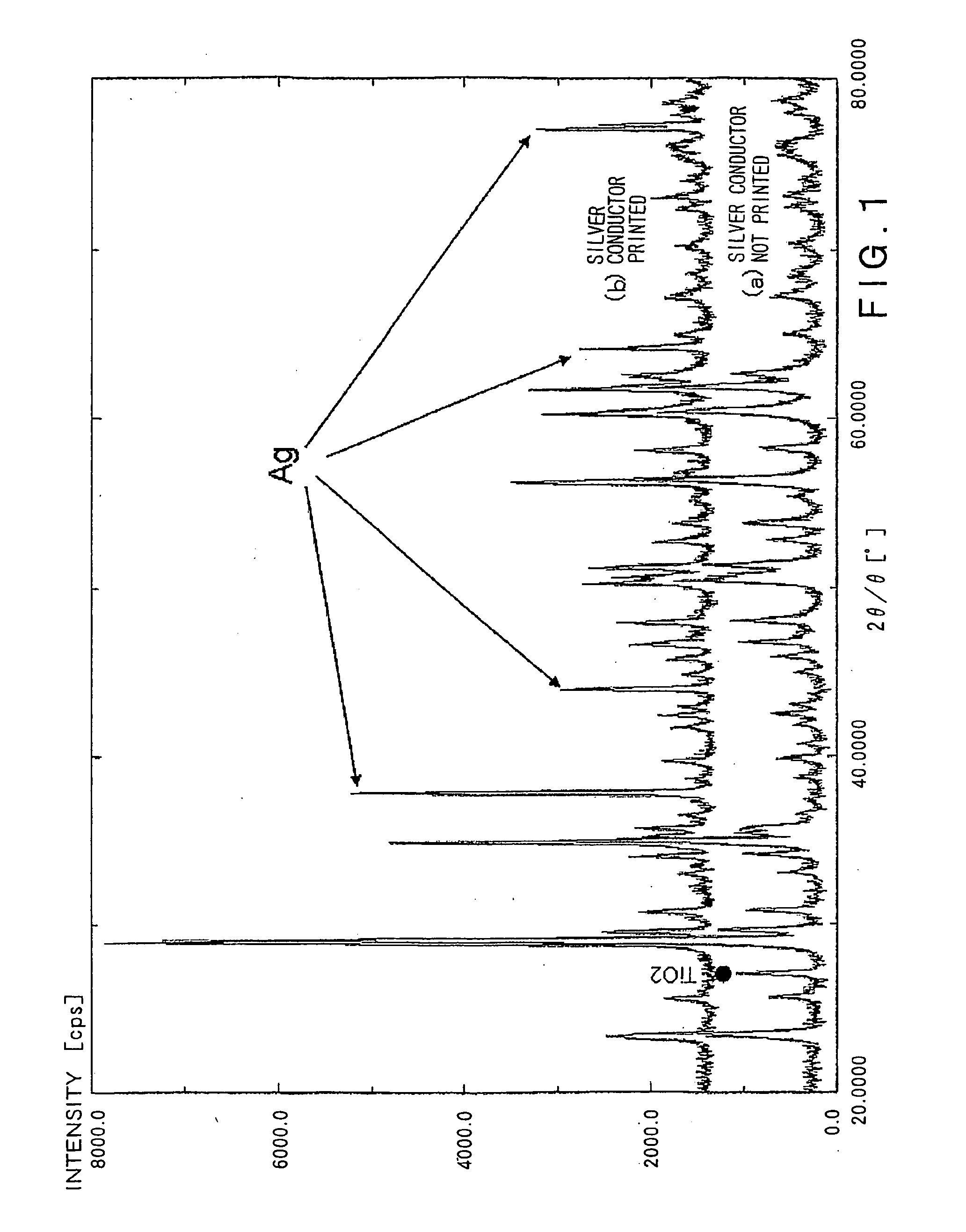
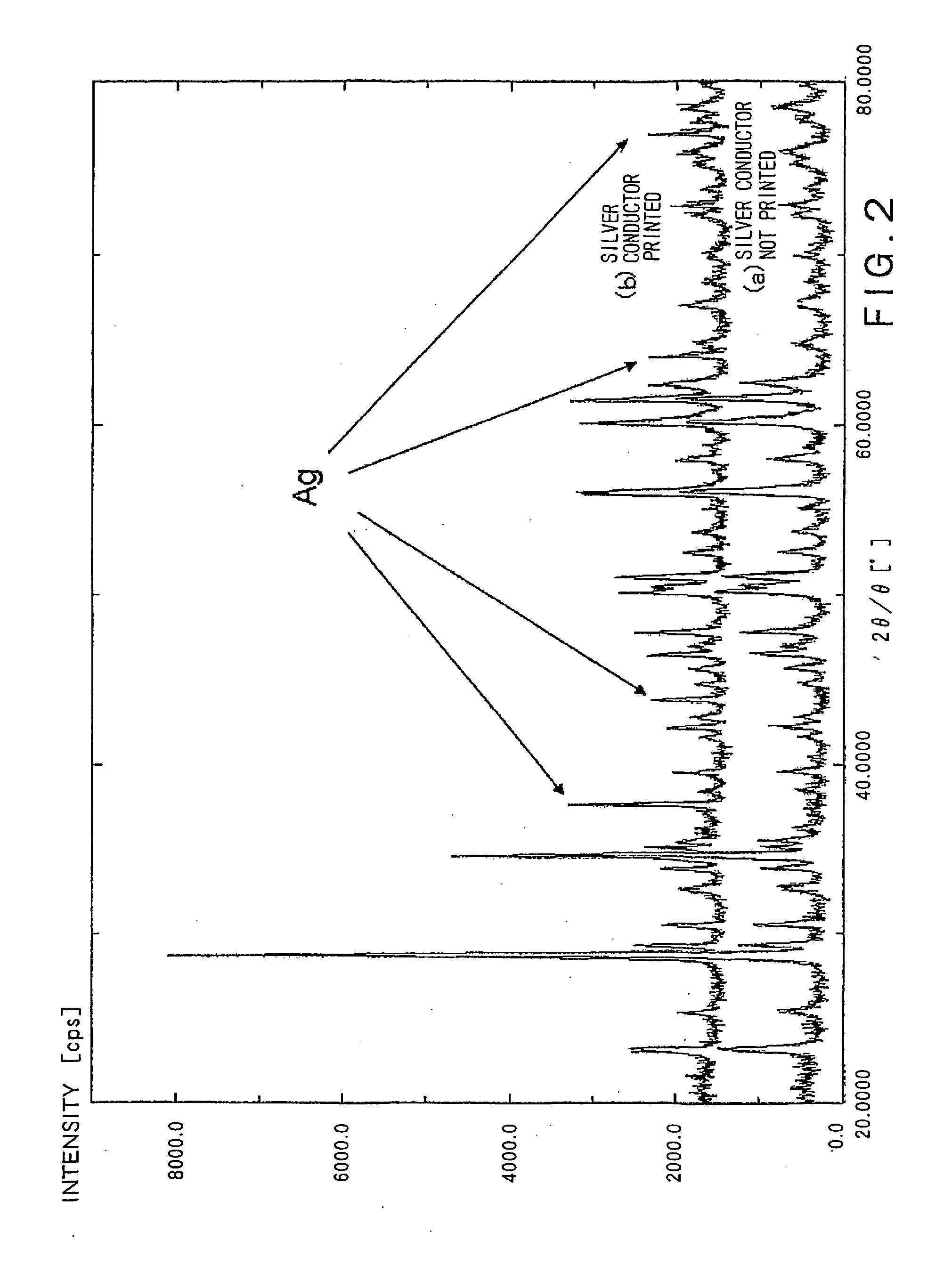
[0010]The dielectric ceramic composition according to the present invention can simultaneously satisfy all the requirements of relative permittivity, frequency-quality factor, and temperature coefficient, can be sintered at a low temperature at or below the melting point of Ag, Cu, or Au as a simple substance or an alloy composed mainly of Ag, Cu, or Au, which is contemplated as an internal conductor material, and can suppress the precipitation of TiO2 crystals by virtue of the addition of CaO and does not have any adverse effect, derived from a chemical reaction between the internal conductor and TiO2, on the internal conductor.
[0011]The dielectric ceramic composition according to the present invention has an additional effect that it can be produced by a simple process. Specifically, since the main component and the accessory component can be calcined together, the production process can be simplified as compared with the conventional process in which an accessory component is added to a previously calcined main component, and the mixture is then subjected to secondary calcination. Further, the recovery of the dielectric ceramic composition can be improved, and the cost can be reduced.

Problems solved by technology

These compositions, however, do not simultaneously satisfy all the above property requirements.
Accordingly, an enhancement in some properties results in deterioration of other properties, and, thus, it has been difficult to produce a composition simultaneously satisfying all the above property requirements.
This material, however, is reactive with silver and cannot be used as a material for low-temperature fired laminated substrates where silver is used as an internal conductor.

Method used


Image

  • Dielectric Ceramic Composition
  • Dielectric Ceramic Composition
  • Dielectric Ceramic Composition

Examples


examples

[0048]The following Examples further illustrate the present invention.

[0049]ZnO, Nb2O5, CaCO3, and CaTiO3 were provided as main component materials, and CuO and B2O3 were provided as accessory component materials. They were weighed in such respective amounts that the mixing ratio among ZnO, Nb2O5, CaCO3, CaTiO3, CuO and B2O3 after firing is as shown in the column of the main component composition in Table 1 below. Pure water was added thereto to a slurry concentration of 30%, followed by wet mixing in a ball mill for 5 hr. The mixture was then dried. The dried powder was calcined in the air at a temperature specified in Table 1 for two hr.

[0050]Pure water was added to the powder thus obtained to a slurry concentration of 30%. The slurry was subjected to wet pulverization in a ball mill for 24 hr, followed by drying to prepare a dielectric material mixture.

[0051]Next, one part by weight of polyvinyl alcohol was added as a binder to 100 parts by weight of each of the dielectric materi...


PUM

PropertyMeasurementUnit
Percent by massaaaaaaaaaa
Temperatureaaaaaaaaaa

Abstract

There is provided a dielectric ceramic composition having a high relative permittivity, a high frequency-quality factor, a small absolute value temperature coefficient, a low sintering temperature, and unreactivity with an internal conductor material. The dielectric ceramic composition comprises a main component represented by general formula xZnOxNlb2O5yCaTiO3zCaO, wherein 37≦x≦50, 10≦y≦60, 3≦z≦40, and x+y+z=100, and a boron (B) oxide as an accessory component in an amount of 0.3 to 3.0 parts by weight in terms of B2O3 based on the main component.

Description

TECHNICAL FIELD[0001]The present invention relates to a dielectric ceramic composition. More particularly, the present invention relates to a dielectric ceramic composition having a high relative permittivity, a high frequency-quality factor, a small absolute value temperature coefficient of resonance frequency, and a low sintering temperature.BACKGROUND OF THE INVENTION[0002]The development of information communication equipment such as mobile communication equipment in recent years has led to an increasing expectation for enhanced performance of dielectric ceramics for microwave applications to meet property requirements of such information communication equipment. Specifically, although properties required of ceramic compositions for dielectric ceramics vary depending upon applications, commonly required properties include high relative permittivity for reducing the size of devices, a high frequency-quality factor for suppressing attenuation, a reduction in absolute value of temp...

Claims


Application Information

Patent Timeline
IPC IPC(8): C04B35/03
CPCC04B35/465C04B35/495C04B35/6263C04B35/62675C04B2235/3208C04B2235/3236H01G4/1254C04B2235/3281C04B2235/3284C04B2235/3409C04B2235/604C04B2235/656H01G4/1227C04B2235/3251
Inventor LUO, SHIYAMAKAWA, TAKAHIRO
Owner YOKOWO CO LTD
Learn More