
Engine for small vehicle

Inactive Publication Date: 2009-04-30
HONDA MOTOR CO LTD
View PDF7 Cites 14 Cited by
  • Summary
  • Abstract
  • Description
  • Claims
  • Application Information

AI Technical Summary

Benefits of technology

[0004]The present invention has been made in consideration of the above-mentioned circumstances, and an object of the present invention is to provide an engine for a small vehicle that increases the degree of freedom in disposing an oil passage between a valve-operation mode changing mechanism and a valve-moving hydraulic pressure control device while avoiding an increase in the number of parts and assembly man-hours.
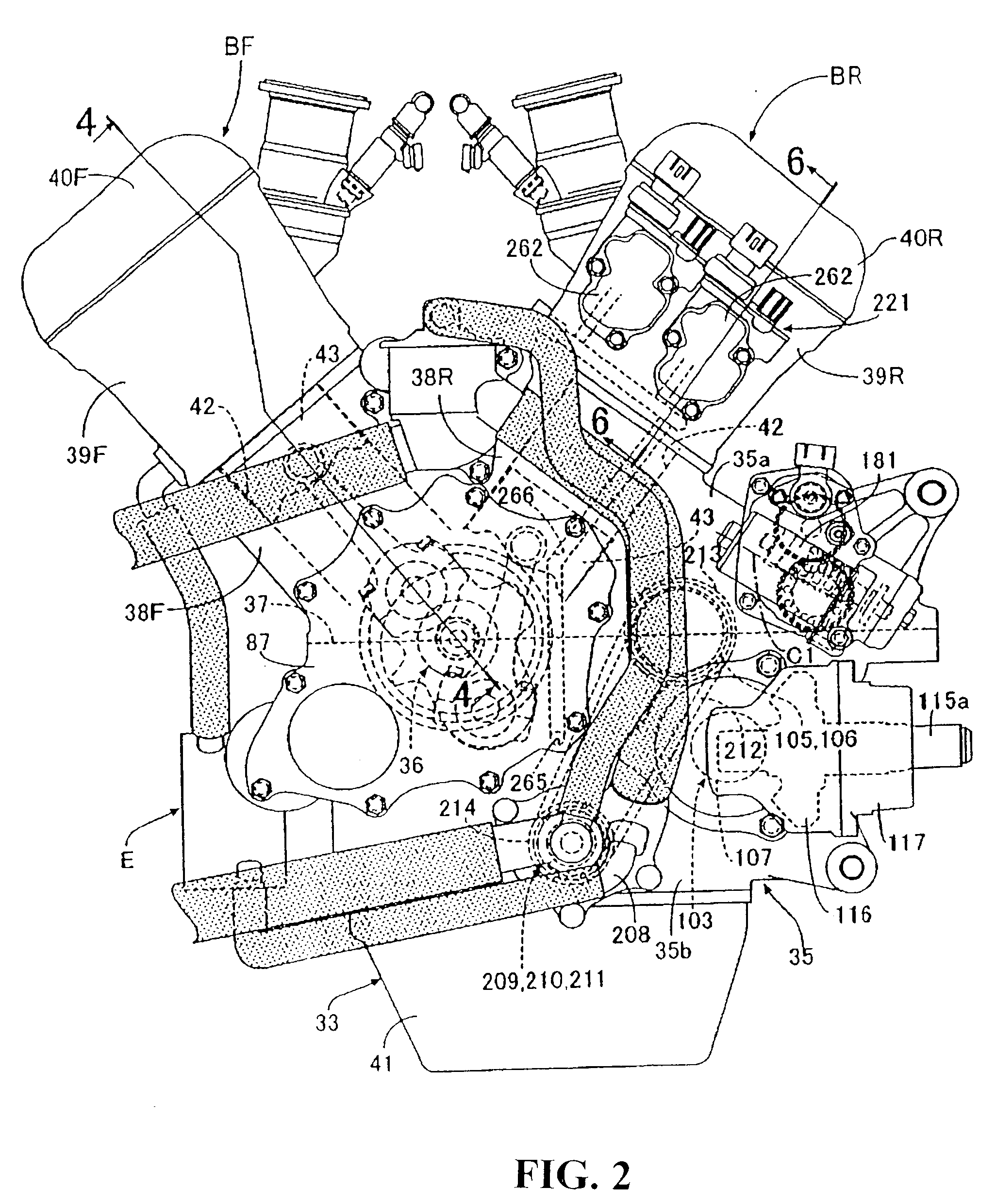
[0010]According to the first aspect, the cam chain is wound around the driven sprockets provided at one end of each camshaft, and the valve-moving hydraulic pressure control device for controlling the hydraulic pressure applied to the valve-operation mode changing mechanisms is mounted on the side surface of the engine body on the side opposite to the cam chain in the axial direction of the camshafts. Accordingly, when the valve-operation mode changing mechanisms and the valve-moving hydraulic pressure control device are connected to each other by the oil passages, it is not necessary to avoid the path of the cam chain. As a result, it is possible to increase the degree of freedom in disposing the oil passage. In addition, it is possible to directly connect the oil passage to the engine body, and to suppress the increase in the number of parts and assembly man-hours.
[0011]Further, according to the second aspect, at least a part of the oil passages, which connect the valve-moving hydraulic pressure control device with an oil pump, is formed in the engine body at the end opposite to the driven sprocket of each of the camshafts. Accordingly, it is possible to simplify the structure of the oil passage that introduces oil into the valve-moving hydraulic pressure control device from the oil pump, and to suppress the increase in the number of parts and processing man-hours.
[0012]According to the third aspect, a recess, which is recessed inward from the coupling surface of the cylinder block and the cylinder head, is formed on the side surface of the cylinder head that corresponds to the ends of the camshafts opposite to the driven sprockets of the camshafts. The valve-moving hydraulic pressure control device is mounted on the side surface of the cylinder head so that a part of the valve-moving hydraulic pressure control device is received in the recess. It is possible to suppress the increase in the bulk of the engine that includes the valve-moving hydraulic pressure control device by mounting the valve-moving hydraulic pressure control device on the engine body, thereby making the engine compact. In addition, according to the fourth aspect, a part of the oil passage connected to the valve-moving hydraulic pressure control device is formed in the cylinder head and the cylinder block so as to overlap the valve-moving hydraulic pressure control device on the side closer to the crankshaft than the recess, as seen in the axial direction of cylinder bores formed on the cylinder block. Accordingly, it is possible to efficiently dispose the oil passage connected to the valve-moving hydraulic pressure control device.

Problems solved by technology

For this reason, it is not easy to dispose the oil passages, and the degree of freedom in disposing the oil passages is decreased.
Further, pipe members, which are individual bodies separated from the engine body, need to be disposed across the cam chain chamber, causing the number of parts and assembly man-hours to be increased.

Method used


Image

  • Engine for small vehicle
  • Engine for small vehicle
  • Engine for small vehicle

Examples


Embodiment Construction

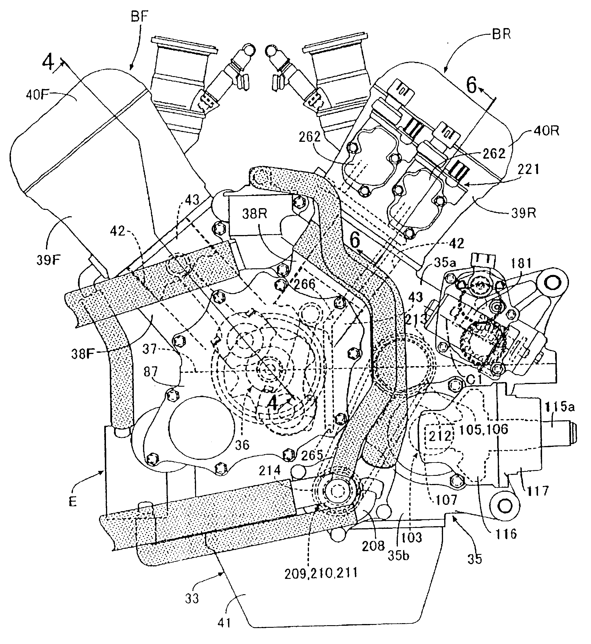
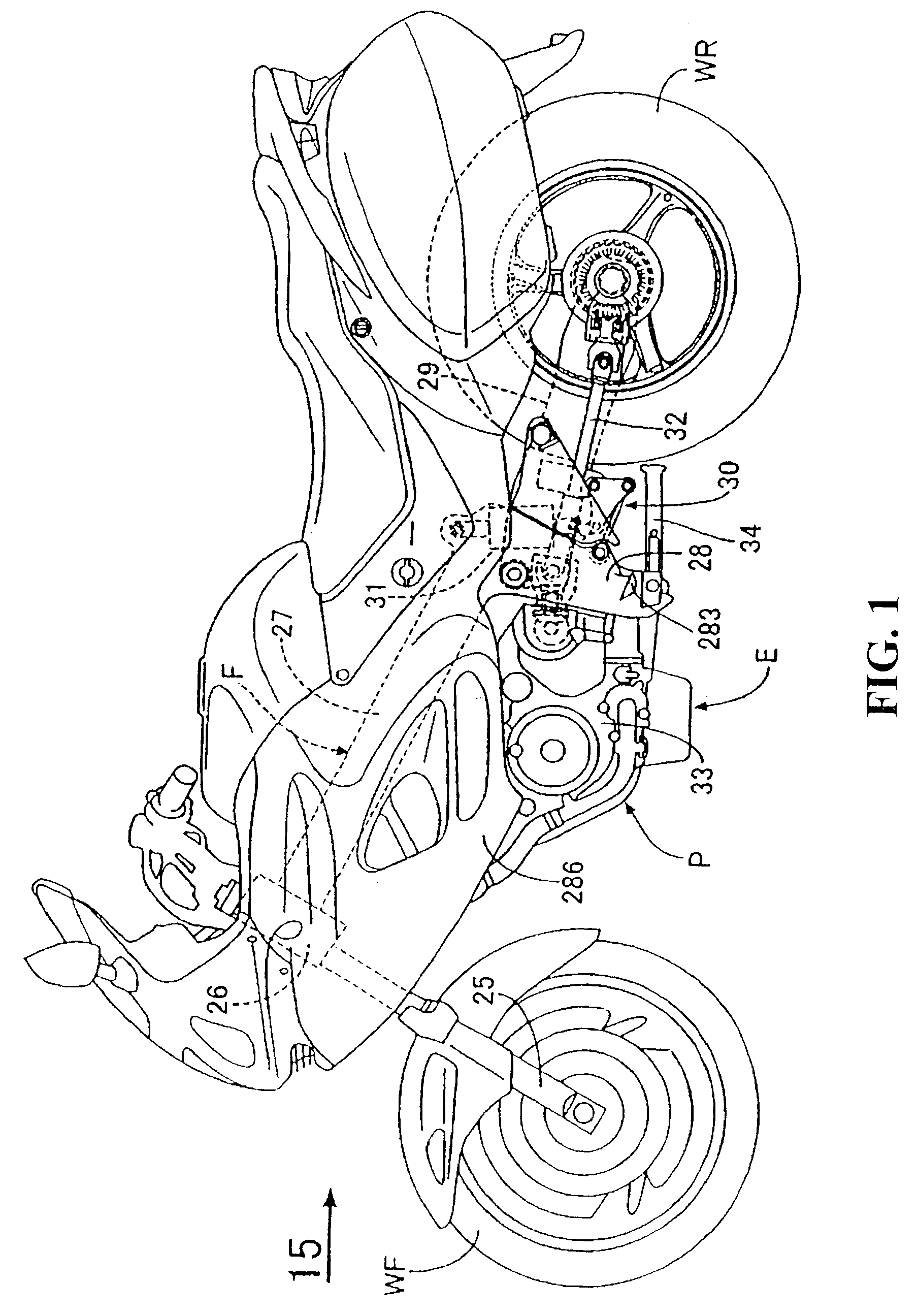
[0030]In FIG. 1, a vehicle body frame F of a motorcycle, which is a saddle-riding type small vehicle, includes a head pipe 26 that is used to steer a front fork 25 pivotally supporting a front wheel WF, a pair of left and right main frames 27 that extend downward from the head pipe 26, and a pair of left and right pivot plates 28 that are connected to the rear portions of both main frames 27 to extend downward. A rear wheel WR is pivotally supported by the rear portions of swing arms 29, of which front ends are swingably supported by the pivot plates 28. In addition, links 30 are provided between the front portions of the swing arms 29 below the pivot plates 28, and a cushion unit 31 is provided between the links 30, above the pivot plates 28.

[0031]A power unit P is suspended from and mounted on the main frames 27 and the pivot plates 28, and rotative power output from the power unit P is transmitted to the rear wheel WR through, for example, a drive shaft 32 extending in a forward ...


PUM


Abstract

There is provided an engine for a small vehicle where driven sprockets, around which a cam chain for transmitting power from a crankshaft is wound, are provided at one end of camshafts that form a part of a valve system provided with hydraulic valve-operation mode changing mechanisms; and a valve-moving hydraulic pressure control device, which controls hydraulic pressure applied to the valve-operation mode changing mechanisms, is provided in the engine body. In the engine, it is possible to increase the degree of freedom in disposing the oil passage between the valve-operation mode changing mechanism and the valve-moving hydraulic pressure control device while avoiding the increase in the number of parts and assembly man-hours. A valve-moving hydraulic pressure control device is mounted on the side surface of the engine body on the side opposite to a cam chain in an axial direction of a camshaft.

Description

TECHNICAL FIELD[0001]The present invention relates to an engine for a small vehicle where camshafts, which form a part of a valve system provided with hydraulic valve-operation mode changing mechanisms for changing operation modes of engine valves, are rotatably supported by a cylinder head; an endless cam chain is wound around a driving sprocket, which is provided on a crankshaft rotatably supported by a crankcase forming a part of an engine body together with the cylinder head, and driven sprockets, which are provided at one end of each camshaft; and a valve-moving hydraulic pressure control device, which controls hydraulic pressure applied to the valve-operation mode changing mechanisms, is provided in the engine body.BACKGROUND OF THE INVENTION[0002]JP-A No. 2006-118512 discloses a structure where an oil control valve, which controls hydraulic pressure applied to an actuator of a hydraulic valve timing changing mechanism for changing operation modes of engine valves, is mounted ...

Claims


Application Information

Patent Timeline
IPC IPC(8): F01L9/02
CPCF01L1/022F01L2810/02F01L1/182F01L1/20F01L13/0005F01L2001/0535F01L2001/0537F01L2105/00F02B61/02F02B67/04F16D21/06F16D25/0638F16D25/10F16D2021/0661F16H61/0003F16H61/0009F01L1/143F01L2305/00
Inventor MAEHARA, HAYATOFUJIMOTO, YASUSHI
Owner HONDA MOTOR CO LTD
Learn More