

Vacuum debris removal system
a vacuum and debris technology, applied in the direction of manufacturing tools, metal working equipment, welding/soldering/cutting articles, etc., to achieve the effect of efficient material removal, rapid debris removal, and optimal speed
Inactive Publication Date: 2009-04-30
ANVIK CORP
View PDF4 Cites 22 Cited by
- Summary
- Abstract
- Description
- Claims
- Application Information
AI Technical Summary
Benefits of technology
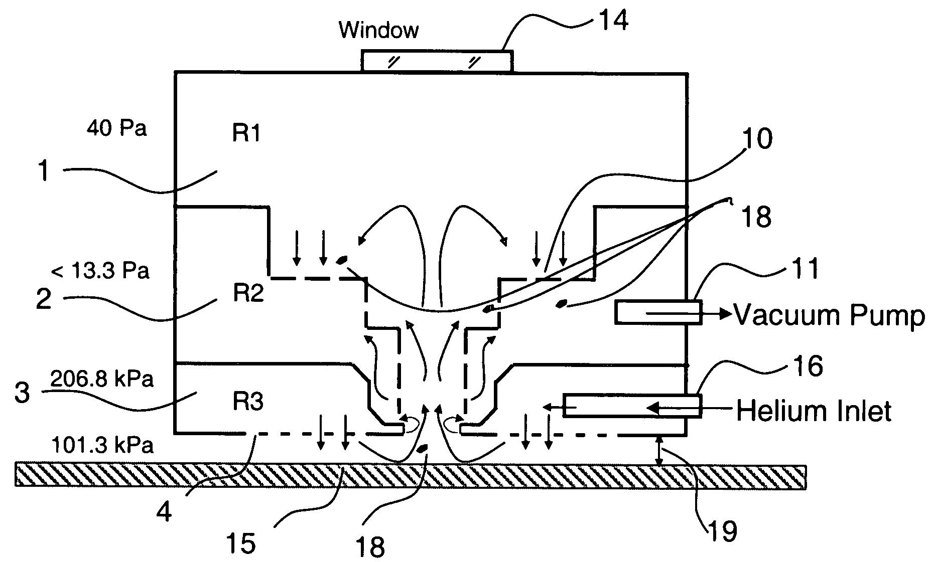
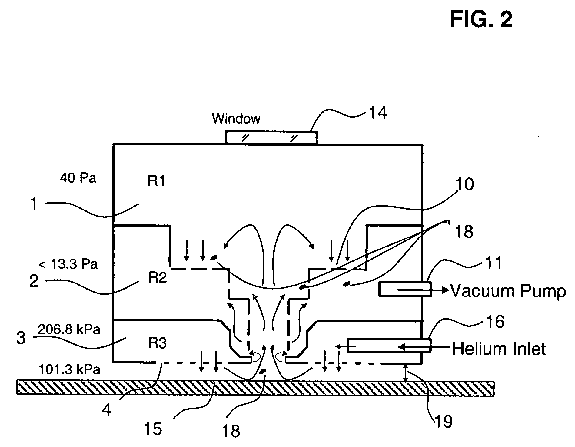
[0009]This invention provides a vacuum debris removal system which can continuously remove debris and gases from the process region. The design of the vacuum debris removal system is such that it envelopes the process region, and especially the ablation site on the currently-positioned substrate, concentrically. This allows the radiation beam to be centered in a relatively large opening about the ablation site, so the radiation beam can go through the center of the radiation site opening while the flushing gas and particulates flow about the inner periphery of the radiation site opening. This concentric configuration enables rapid debris removal between pulses and provides a debris-free region for effective material removal using a laser. The flow is directed by differential vacuum partial pressure, and conductances all the way from vacuum pump (lowest partial pressure) to the orifice around the ablation site is designed and calculated such that an optimal speed and vacuum pressure for effective removal is obtained. The throughput of the process is related to speed of traversal and by the rate of ablation or other removal process, but they in turn depend directly on the effective removal of microscopic material before they agglomerate into macro particles and hinder material removal.
[0011]A feature of this invention is the use of multiple chambers with metering orifices to optimize vacuum partial pressure differentials for the desired sweeping flow. However, this also enables customization for different substrates held by vacuum chucks, and deliver optimal vacuum partial pressures for effective debris removal.
[0013]Another feature of the system is that it is designed to surround the ablation site and the chambers of the ablation region from all sides, making it the most effective design for debris removal.
[0015]An advantage of this invention is that a virtual chamber formed by the closely-spaced current substrate and the bottom surface of the adjacent metering chamber enclose an envelope of sweeping gas around the ablation site, which keeps ablation debris from escaping to another location on the substrate, but Instead curtail ablation particulate drifting and deliver ablation particulates from the current substrate into the mouth of the ablation orifice in the adjacent metering chamber.
Problems solved by technology
This is of prime concern due to the ineffectiveness of the debris removal systems acting across the ablation site from the sides.
Method used
View moreImage
Smart ImageViewing Examples

Examples
casea
C(fromSbst→R1→R2)=1 / [1CS→R1+1CR1→R2]=1 / [126.55+119]=1 / [119]Casea:C(fromSbst→R1→R2)=11.07sCaseb:C(fromSbst→R1→R2)=13.91sC(fromSbst→R2)=11.86s
Case a: CVP=22.93 l / s and case b: CVP=25 l / s
In fact, reducing the requirement for higher flow rate from the vacuum pump and in turn providing a range of velocities for effective debris removal.
DRS Gap
[0051]DRS gap and control of velocity, in turn controlling force required in picking up of debris is equally important in comparison with maintaining of desired conductance.
Throughput Q=C*□P
=C*F / A since, difference in pressure=Force per unit area
F=(Q*A) / C
=throughput*area / conductance
Login to View More PUM
| Property | Measurement | Unit |
|---|---|---|
| Partial pressure | aaaaa | aaaaa |
| Ablation enthalpy | aaaaa | aaaaa |
Abstract
A turbulence-controlled vacuum debris removal subsystem safely exhausts particles ejected during photoablation. Nested interconnected chambers provide diminishing sweeping gas partial pressure and diminishing turbulence, ejecting particles from the ablation beam path between pulses, without compromising continuing particle conductance. Removal rate (debris generation rate) depends on conductance and particle sizes. The chambers interconnect through metering holes which enable optimization of partial pressure differentials. Controlled flow accomplishes debris removal, reducing turbulence of the mixture of debris and sweeping gases. A preferred embodiment uses a nest of concentric chambers, providing a clear light path. Another preferred embodiment uses orifices on chamber faces for removal and forming an envelope of gas around the processing region for dynamically containing the ejected particulate matter from the ablation site to the exhaust.
Description
BACKGROUND OF THE INVENTION[0001](1) Field of the Invention[0002]The present invention relates to an inert gas debris removal subsystem to carry off particulate contaminants from the radiation-ablated region of a substrate being treated in a photo-ablation system. and specially relates to such a subsystem with multiple chambers having openings which meter a flow of inert gas in a plurality of chambers through openings for controlled partial pressure differentials in such chambers for particulate-flushing gas flow which does not interfere with the ablation beam or cause contaminant build-up.[0003](2) Description of Related Art[0004]Semiconductor devices and integrated circuits are manufactured using multiple layers of different types of materials. These conductive, semi-conductive and insulation type material are deposited or formed on substrate, semiconductor die, wafer, may be used even simply on their own. The predetermined patterns for packaging electronics, biomaterials, etc are...
Claims
Login to View More Application Information
Patent Timeline
 IPC IPC(8): B23K26/16B23K26/36
CPCB23K26/063B23K26/1476B23K2201/40B23K26/4075B23K26/16B23K26/40B23K26/0622B23K2101/40B23K2103/50
InventorWOJCIK, LESZEKWOJCIK, DIWAKARJAIN, KANLIKUCHIBHOTLA, SIVARAMA K.PANNEERSELVAM, ARUN
OwnerANVIK CORP