Material assisted laser ablation

a laser ablation and laser technology, applied in the field of material assisted laser ablation, can solve the problems of affecting the commercial implementation of nanotube-based electronic systems, and the physical and electronic characteristics of carbon nanotubes deposited by electrophoresis may not be sufficient to support applications in high-performance electronics, etc., to facilitate their integration, low fluence conditions, easy to remove through developing

Active Publication Date: 2013-10-01
THE BOARD OF TRUSTEES OF THE UNIV OF ILLINOIS
View PDF55 Cites 3 Cited by
  • Summary
  • Abstract
  • Description
  • Claims
  • Application Information

AI Technical Summary

Benefits of technology

[0014]Methods of the present invention provide a high-throughput, low cost, patterning platform for porous and / or nano-structured materials that is an alternative to conventional photolithography and direct laser ablation patterning techniques. The present methods are compatible with a range of patterned materials, including porous and / or nano-structured materials. The present methods extend the applicability of patterning via laser ablation to materials are that are especially difficult to pattern via direct laser ablation due to their chemical or physical properties (e.g., high chemical stability), such as nanotubes (e.g., carbon nanotubes, SWNTs, MWNTs), nanowires (e.g., semiconducting, metallic or dielectric nanowires) and other nanoparticles, and are capable of making patterns exhibiting high resolution, good pattern fidelity and high precision. Processing provided by the present methods is compatible with large area patterning of substrates, such as device substrates for semiconductor integrated circuits, displays, and macroelectronic device arrays and systems, and is useful for fabrication applications requiring patterning of layered materials, such as patterning thin film layers of nanomaterials, such as nanotubes and nanowires, in thin film electronic devices. The processing methods of the present invention can be implemented with a range of substrates including semiconductor substrates, ceramic substrates, optically transparent substrates, flexible substrates (e.g., polymers) and device substrates prepatterned with electronic device components. Processing methods of the present invention are complementary to conventional microfabrication and nanofabrication methods for making integrated electronics, and can be effectively integrated into existing photolithographic, etching, and thin film deposition patterning systems, processes and infrastructure.
[0029]Photoablation removal of target material can be achieved using electromagnetic radiation in the ultraviolet, visible and near infrared regions of the electromagnetic spectrum. In an embodiment, the exposing step is carried out using electromagnetic radiation having wavelengths selected over the range 100 nm to 1500 nm. Photoablation removal of target material can be achieved using pulsed or continuous exposure to electromagnetic radiation having wavelengths and energies (e.g. fluence) capable of initiating ablation of the photoablation assisting material. Photoablation provides a very high degree of control over the physical dimensions and spatial orientations of removed regions of the layer of target material, thus enabling making high resolution patterns exhibiting good pattern fidelity. A range of optical sources can be used for ablation in the present invention including diode lasers, HeNe laser, rare-gas ion lasers (Ar-ion laser, Kr-ion laser), Metal vapor lasers (HeCd laser, Copper-vapor laser, Gold-vapor laser), Carbon dioxide laser, Carbon monoxide laser, Excimer lasers (F2 laser, ArF laser, KrCl laser, KrF laser, XeCl laser, XeF laser), nitrogen laser, and Chemical lasers.

Problems solved by technology

Given their high degree of chemical and physical stability, conventional patterning techniques are inadequate to fully support commercial implementation of nanotube-based electronic systems.
The processing strategy described by Choi et al. is susceptible to significant drawbacks, however, that hinder its commercial implementation.
Also, it is expected that the physical and electronic characteristics of carbon nanotubes deposited by electrophoresis may not be sufficient to support applications in high performance electronics, as it is generally accepted that carbon nanotubes grown by high temperature chemical vapor deposition (CVD) techniques have superior properties.
While the method is reported to provide a pattern having reasonable fidelity on the device substrate, the deposited carbon nanotubes are also likely to have inferior electronic and physical properties relative to methods using CVD to generate nanotubes directly on the substrate.
The screen-printing approach is also likely to be susceptible to problems arising from low pattern resolution and inefficient use of the carbon nanotube material.
Similar to the work of Choi et al., although patterning was achieved, the deposited carbon nanotubes are likely to have inferior electronic and physical properties relative to methods using CVD to generate nanotubes directly on the substrate undergoing processing.
A disadvantage of this technique is that selective removal of the carbon nanotubes using oxygen plasma requires long processing times, which hinders commercial implementation of this technique.

Method used


Image

  • Material assisted laser ablation
  • Material assisted laser ablation
  • Material assisted laser ablation

Examples


example 1

Patterning of Single Walled Carbon Nanotubes Using a Low-Fluence Excimer Laser Photoablation Process

[0061]Abstract

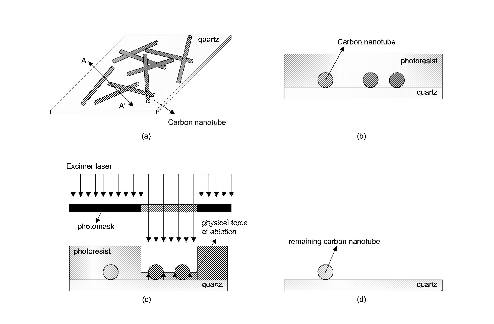
[0062]Carbon nanotube films were patterned by an excimer laser projection photoablation process at low incident energy conditions. The carbon nanotubes were deposited on a quartz substrate, and then a conventional photoresist was coated on it as a photoablation assisting material. The photoresist and the carbon nanotubes were patterned simultaneously by the projection photoablation process, and then the photoresist was removed. Due to the physical force of the ablation process, the carbon nanotubes were patterned cleanly even though the incident fluence on the carbon nanotubes was significantly lower than the threshold energy otherwise needed for their direct ablation.

[0063]Experimental Results

[0064]Carbon nanotubes have been researched as a possible important new component in various devices because they have a promising potential in applications such as microelectronic...

example 2

Patterning of Porous Materials

[0088]Porous materials are important components used in sensors and biomedical applications. The present invention provides processing capable of patterning porous target materials, including porous materials that are difficult to pattern via direct laser ablation methods. In some embodiments, an AMM layer is provided in contact with the porous target material in a manner such that the PAM is provided under the porous material or within the pores of the porous material. Upon exposure to electromagnetic radiation having sufficient wavelengths and fluences to initiate ablation of the AMM, forces generated during ablation result in removal of porous material integrated with the PAM.

example 3

Removal of Photoablation Debris and / or Byproducts After or During Photoablation

[0089]The present invention includes processing wherein photoablation debris generated by photoablation of the photoablation assisting material and target material is removed via one or more processing steps. This aspect of the present invention is particularly useful for patterning in nano- and micro-electronics applications wherein such photoablation debris can degrade performance.

[0090]After photoablation of photoablation assisting materials, such as polymers and / or photoresist, thin layer (monolayer or some layers of hydrocarbon byproducts) of photoablation debris (e.g., residue and / or byproducts) can remain on the ablated area. For example, some debris remains after ablation of photoresist as shown in FIG. 7(a) and 7(b). FIGS. 7a and 7b provide optical microscopic photographs of patterned photoresist. The incident excimer laser fluence was 50 mJ cm−2 and the number of pulses was 40. FIG. 7a shows pat...


PUM

PropertyMeasurementUnit
thicknessaaaaaaaaaa
viscosityaaaaaaaaaa
thicknessaaaaaaaaaa

Abstract

This invention provides photoablation—based processing techniques and materials strategies for making, assembling and integrating patterns of materials for the fabrication of electronic, optical and opto-electronic devices. Processing techniques of the present invention enable high resolution and / or large area patterning and integration of porous and / or nano- or micro-structured materials comprising active or passive components of a range of electronic devices, including integrated circuits (IC), microelectronic and macroelectronic systems, microfluidic devices, biomedical devices, sensing devices and device arrays, and nano- and microelectromechanical systems.

Description

CROSS-REFERENCE TO RELATED APPLICATIONS[0001]Not applicable.STATEMENT REGARDING FEDERALLY SPONSORED RESEARCH OR DEVELOPMENT[0002]Not Applicable.BACKGROUND OF INVENTION[0003]A great deal of research has been directed over the last several decades toward characterizing the composition and properties of carbon nanomaterials, and developing efficient pathways for making, purifying and using this unique class of materials. The extraordinary mechanical, electronic and chemical properties of carbon nanotubes, for example, have stimulated significant interest in developing applied technologies exploiting these useful properties. As a result, carbon nanotubes are currently identified as a promising class of functional materials for electronic and opto-electronic systems, and there is substantial interest in developing advanced techniques for integrating carbon nanotube materials into useful devices and systems.[0004]Carbon nanotubes are allotropes of carbon comprising one or more cylindrical...

Claims


Application Information

Patent Timeline
Patent Type & Authority Patents(United States)
IPC IPC(8): G03F7/20
CPCB23K26/0066B23K26/18B23K26/4005B23K26/401B23K26/4065B23K26/407B23K26/408B81C1/00634B82Y20/00B82Y30/00G03F7/202H01L21/3213B23K26/0009B23K26/0036B23K26/0039B23K26/0042B23K26/0045B23K26/0006B23K26/40B23K26/352B23K2103/08B23K2103/42B23K2103/50B23K2103/52B23K2103/56Y10T428/24802
Inventor JAIN, KANTICHAE, JUNGHUN
Owner THE BOARD OF TRUSTEES OF THE UNIV OF ILLINOIS
Why Eureka
Try Eureka