Icing protection system and method for enhancing heat transfer

a technology of icing protection system and heat transfer, which is applied in the direction of heat exchange apparatus safety devices, light and heating equipment, propellers, etc., can solve the problems of increasing drag, adding weight, and ice formation on aircraft structures, and achieve the effect of enhancing heat transfer

Inactive Publication Date: 2009-04-30
GENERAL ELECTRIC CO
View PDF15 Cites 27 Cited by
  • Summary
  • Abstract
  • Description
  • Claims
  • Application Information

AI Technical Summary

Benefits of technology

[0010]The above mentioned needs and others that will be readily apparent to those skilled in the art are met by the invention, which in one aspect provides an icing protection system for preventing the formation of ice on a surface that is susceptible to icing. The icing protection system includes a substrate having a first outer surface, a second inner surface opposite the first surface and a thickness separating the first surface and the second surface. The icing protection system further includes a metallic layer deposited on the inner surface of the substrate. The metallic layer is operable for enhancing heat transfer from the compressor bleed air in flow contact with the metallic layer through the thickness of the substrate to prevent the formation of ice on the outer surface.
[0011]According to another aspect, the invention provides a method for enhancing heat transfer to a surface that is susceptible to icing. The method includes providing a substrate having a first outer surface, a second inner surface opposite the first surface, and a thickness separating the first surface and the second surface. The method further includes depositing a metallic layer on the inner surface and dispersing a heated gas in flow communication with the metallic layer to enhance heat transfer from the heated gas through the thickness of the substrate and thereby prevent the formation of ice on the outer surface.
[0012]According to another aspect, the invention provides an icing protection system for preventing the formation of ice on an aircraft structure that is susceptible to icing and for enhancing heat transfer in the aircraft structure. The icing protection system includes a substrate having an inner surface, an outer surface opposite the inner surface and a thickness separating the inner surface and the outer surface. The icing protection system further includes a metallic layer deposited on the inner surface by an electric arc thermal spray deposition process. The metallic layer defines a plurality of micro-fins operable for enhancing heat transfer from a heated gas in flow communication with the metallic layer through the thickness of the substrate to prevent the formation of ice on the outer surface.

Problems solved by technology

The formation of ice on aircraft structures, for example engine inlets, wings, control surfaces, propellers, booster inlet vanes, inlet frames, etc., has been a formidable problem since the inception of heavier-than-air flight.
Ice adds weight, increases drag and alters the aerodynamic contour of airfoils, control surfaces and inlets, all of which reduce performance and consequently increase the specific filet consumption (SFC) of a gas turbine engine.
In addition, ice permitted to form on aircraft structures can become dislodged and impact other aircraft parts and engine components, causing significant structural damage.
For example, fragments of ice can break loose from the engine inlet and could severely damage rotating fan blades and other internal engine components.
In severe instances, the damage that results from ice fragment impacts may lead to engine stall and could even cause engine failure.
Simply delivering the heated air to the nacelle inlet, however, does not allow for sufficient heat energy to be extracted from the compressor bleed air prior to the spent air being exhausted overboard.
Accordingly, it is impractical to utilize turbulators of the type disclosed by Spring et al. to enhance heat transfer to the exterior surface of an aircraft structure that is susceptible to icing.
Use of such an outer metallic layer coated onto a substrate by an electric arc thermal spray deposition process, however, has been limited to date for the purpose of augmenting heat transfer to remove heat from an internal component of a gas turbine engine operating at high temperatures.

Method used


Image

  • Icing protection system and method for enhancing heat transfer
  • Icing protection system and method for enhancing heat transfer
  • Icing protection system and method for enhancing heat transfer

Examples


Embodiment Construction

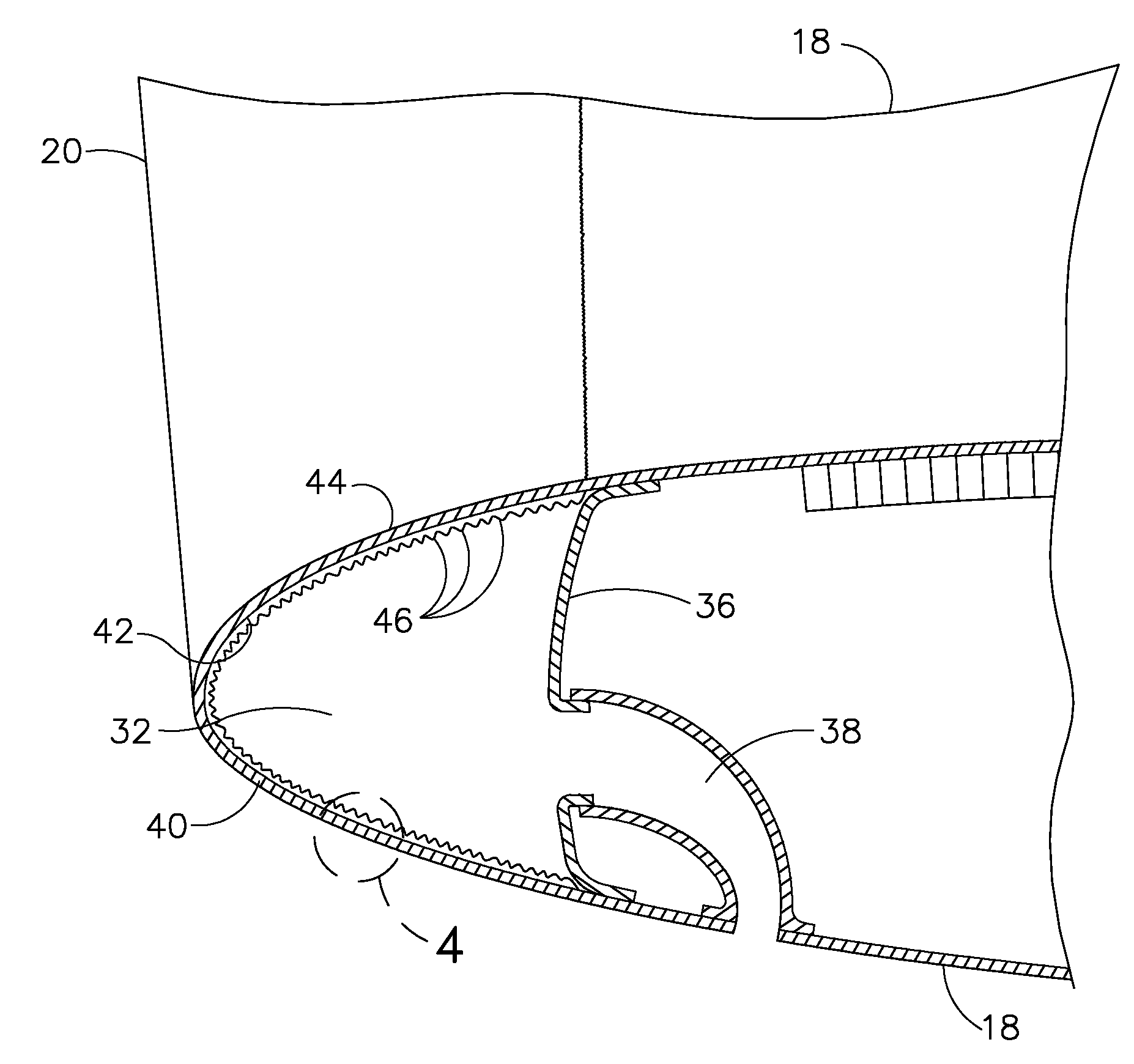
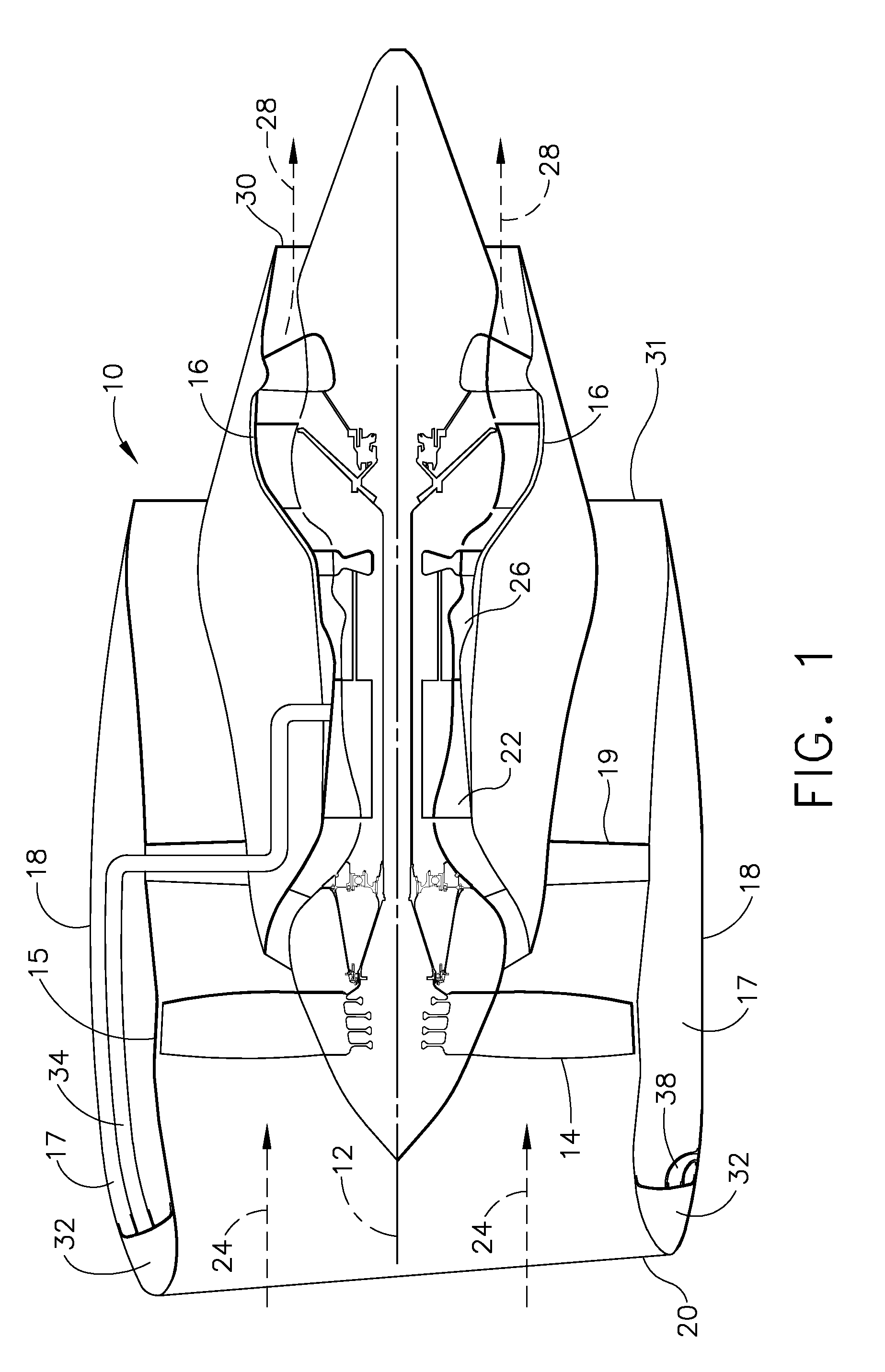
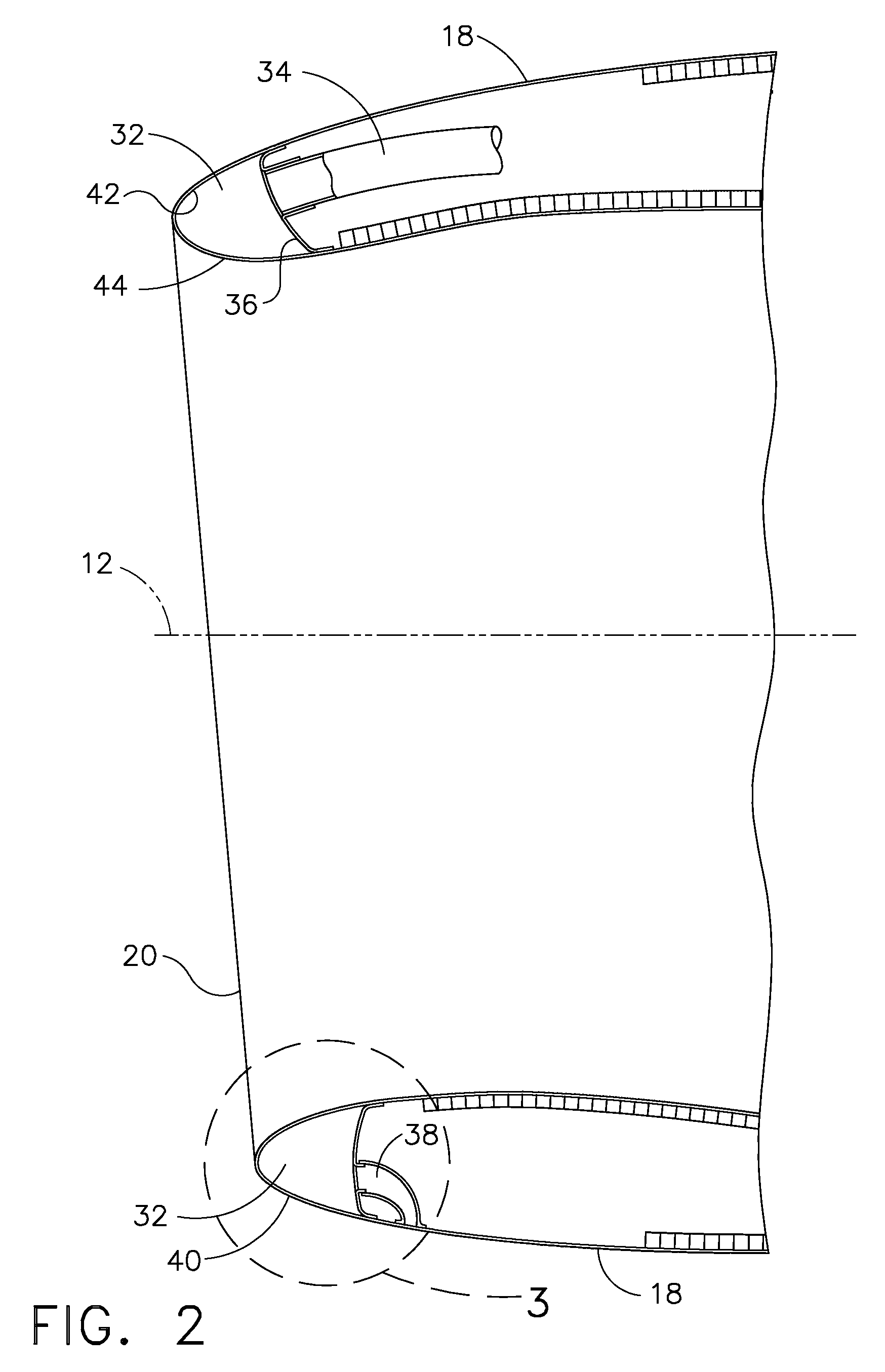
[0023]Referring to the drawings in which identical reference numerals denote the same elements throughout the various views, FIG. 1 illustrates schematically a gas turbine engine, indicated generally at 10, of the type typically utilized to power modern aircraft. The engine 10 is symmetrical about a longitudinal axis 12 and includes a fan 14 powered by a core engine 16. The fan 14 includes a plurality of fan blades rotatably mounted within an annular fan casing 15 that surrounds the fan and at least a portion of the core engine 16. The “engine inlet” or “nacelle inlet”20 of the engine 10 is mounted to the forward flange of the fan casing 15. The core engine 16 includes a multistage compressor 22 having sequential stages of stator vanes and / or rotor blades that pressurize an incoming flow of air 24. The pressurized air discharged from the compressor 22 is mixed with fuel in the combustor 26 of the core engine 16 to generate hot combustion gases 28 that flow downstream through one or ...


PUM

PropertyMeasurementUnit
surface roughnessaaaaaaaaaa
thicknessaaaaaaaaaa
surface roughnessaaaaaaaaaa

Abstract

An icing protection system and method for enhancing heat transfer includes a substrate having an inner wall, an outer wall and a thickness separating the inner wall and the outer wall. A metallic layer deposited on the inner wall of the substrate by an electric arc thermal spray deposition process using at least one metallic wire has a thickness between about 0.203 mm (0.008 inches) and about 0.432 mm (0.017 inches), a surface roughness greater than about 12.7 microns (500 micro-inches) Ra, and a heat transfer augmentation of at least about 1.1. The metallic layer is formed on the inner wall from an M-Cr—Al alloy where M is selected from Fe, Co and Ni. The metallic layer defines a plurality of turbulators that act as micro-fins to enhance heat transfer from a heated gas in flow communication with the metallic layer through the substrate to prevent the formation of ice on the outer wall.

Description

BACKGROUND OF THE INVENTION[0001]This subject matter of this application relates generally to icing protection for aircraft structures, and more particularly, to an icing protection system and method for enhancing heat transfer in aircraft structures that are susceptible to icing.[0002]The formation of ice on aircraft structures, for example engine inlets, wings, control surfaces, propellers, booster inlet vanes, inlet frames, etc., has been a formidable problem since the inception of heavier-than-air flight. Ice adds weight, increases drag and alters the aerodynamic contour of airfoils, control surfaces and inlets, all of which reduce performance and consequently increase the specific filet consumption (SFC) of a gas turbine engine. In addition, ice permitted to form on aircraft structures can become dislodged and impact other aircraft parts and engine components, causing significant structural damage. For example, fragments of ice can break loose from the engine inlet and could se...

Claims


Application Information

Patent Timeline
Patent Type & Authority Applications(United States)
IPC IPC(8): B64D15/02B64D15/04
CPCB64D15/04B64D2033/0233F28F2265/14C23C4/125F28F13/185C23C4/085C23C4/131C23C4/073
Inventor THODIYIL, JOSEPH ALBERTLABORIE, DANIEL JEAN-LOUISSKOOG, ANDREW JAYTOMLINSON, THOMAS JOHN
Owner GENERAL ELECTRIC CO
Why Eureka
Try Eureka