CMOS Detector with Reduced Sensitivity to X-Rays

Inactive Publication Date: 2009-04-30
BAE SYST IMAGING SOLUTIONS
View PDF8 Cites 9 Cited by
  • Summary
  • Abstract
  • Description
  • Claims
  • Application Information

AI Technical Summary

Benefits of technology

[0010]The present invention includes an imaging array and method for operating the same to reduce background caused by x-ray exposure of the imaging array. The imaging array includes a semiconductor substrate having an epitaxial layer of semiconductor material deposited on a first surface thereof. A plurality of photodiodes is formed in a top surface of the epitaxial layer. The imaging array also includes a depletion layer underlying the photodiodes and disposed between the epitaxial layer and the semiconduc

Problems solved by technology

While this method has been in use for many years, it has its disadvantages.
First, the patient is exposed to a significant dose of x-rays.
Second, the time, cost, and equipment needed to process the film increases the cost of the dental examination.
Third, the chemicals utilized in processing the film pose a disposal problem.
These problems have led to several attempts to replace the film component of the traditional x-ray examination with a solid-state sensor that is placed in the patient's mouth to record the x-ray image.
Unfortunately, these sensors are much thicker than the conventional film based sensors and the resolution of the sensors is also less than that of conventional film-based sensors.
The probability of such a conversion event is small, and hence, the x-ray hits result in scattered bright pixels in the image that render the image objectionable.
While the shielding layer solves the bright pixel problem, it introduces new problems.
The increased thickness is objectionable to many patients.
In addition, the cost of the shielding plate is a significant fraction of the cost of the dental sensor.
This layer of lead further increases the system thickness, and also poses both health and environmental concerns if

Method used


Image

  • CMOS Detector with Reduced Sensitivity to X-Rays
  • CMOS Detector with Reduced Sensitivity to X-Rays
  • CMOS Detector with Reduced Sensitivity to X-Rays

Examples


Embodiment Construction

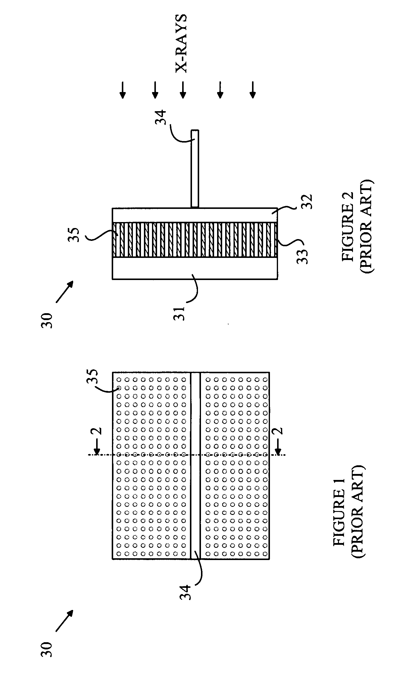
[0018]The manner in which the present invention provides its advantages can be more easily understood with reference to FIGS. 1 and 2, which illustrate a prior art dental sensor. FIG. 1 is a top view of dental sensor 30, and FIG. 2 is a cross-sectional view through line 2-2 shown in FIG. 1. Dental sensor 30 includes a layer 32 of scintillation material that converts x-rays to light in the visible region of the spectrum. The light generated in layer 32 is viewed by an image sensor 31 through a channel plate 33 that consists of a bundle of optical fibers that map the surface of the scintillation material onto image sensor 31. Sensor 30 is placed inside the patient's mouth and held in place by the patient biting down on tab 34. When x-rays from a source outside the mouth impinge on sensor 30 after passing through the patient's teeth, the x-rays strike layer 32. Each interaction between an X-ray and the material of layer 32 results in multiple visible photons being generated. The photon...


PUM


Abstract

An imaging array and method for operating the same is disclosed. The imaging array includes a semiconductor substrate having an epitaxial layer of semiconductor material deposited on a first surface thereof. A plurality of photodiodes is formed in a top surface of the epitaxial layer. The imaging array also includes a depletion layer underlying the photodiodes and disposed between the epitaxial layer and the semiconductor substrate. The depletion layer is connected to a power rail for removing electrons collected in the depletion layer. The depletion layer collects electrons generated by x-ray interactions in the substrate. The depletion layer can also be biased such that the depletion layer collects electrons collected by the photodiodes to provide a reset operation for the imaging array. The current flowing through the depletion layer can be used to generate a trigger signal indicating the start of an x-ray exposure.

Description

BACKGROUND OF THE INVENTION [0001]Dental x-rays are typically taken with a film that is placed in the patient's mouth. The film is exposed through the teeth by an x-ray source that resides outside the patient's head. While this method has been in use for many years, it has its disadvantages. First, the patient is exposed to a significant dose of x-rays. This dose is accumulative over the patient's lifetime. Second, the time, cost, and equipment needed to process the film increases the cost of the dental examination. Third, the chemicals utilized in processing the film pose a disposal problem.[0002]These problems have led to several attempts to replace the film component of the traditional x-ray examination with a solid-state sensor that is placed in the patient's mouth to record the x-ray image. In such systems, a layer of scintillation material is used to convert the x-rays to visible light. The visible light is then imaged onto a solid-state imaging array. Since solid-state x-ray ...

Claims


Application Information

Patent Timeline
IPC IPC(8): H01L31/062H01L25/00
CPCH01L27/14663H01L27/14609
Inventor LIU, XINQIAO
Owner BAE SYST IMAGING SOLUTIONS
Why Eureka
Try Eureka