Control Device and Corresponding Control Method for a Boost Converter in a Motor Drive System

a technology of motor drive system and control device, which is applied in the direction of motor/generator/converter stopper, dynamo-electric converter control, instruments, etc., can solve the problems of not disclosing the control of the boost converter, excessive electric power may be supplied, and a lot of electric power to be consumed in the motor which drives the wheels, so as to prevent the effect of overvoltage of the inverter adequately

Active Publication Date: 2009-04-30
DENSO CORP
View PDF3 Cites 58 Cited by
  • Summary
  • Abstract
  • Description
  • Claims
  • Application Information

AI Technical Summary

Benefits of technology

[0020]According to the present invention, an overvoltage of the inverter can be prevented adequately.

Problems solved by technology

Since the output power is proportional to the torque×the rotation speed, the slipping state causes a lot of electric power to be consumed in the motor which drives the wheels.
In such a configuration including the boost converter, when the rotation speed of the motor rapidly decreases, excessive electric power may be supplied from the boost converter to the inverter.
Japanese Patent Laying-Open No. 2001-295676 does not disclose the control of the boost converter performed in the case of such a change from the slipping state to the gripping state.

Method used


Image

  • Control Device and Corresponding Control Method for a Boost Converter in a Motor Drive System
  • Control Device and Corresponding Control Method for a Boost Converter in a Motor Drive System
  • Control Device and Corresponding Control Method for a Boost Converter in a Motor Drive System

Examples


Embodiment Construction

[0030]The embodiments of the present invention will be hereinafter described in detail with reference to the drawings, in which the same or corresponding components in each figure are designated by the same reference characters, and description thereof will not be repeated.

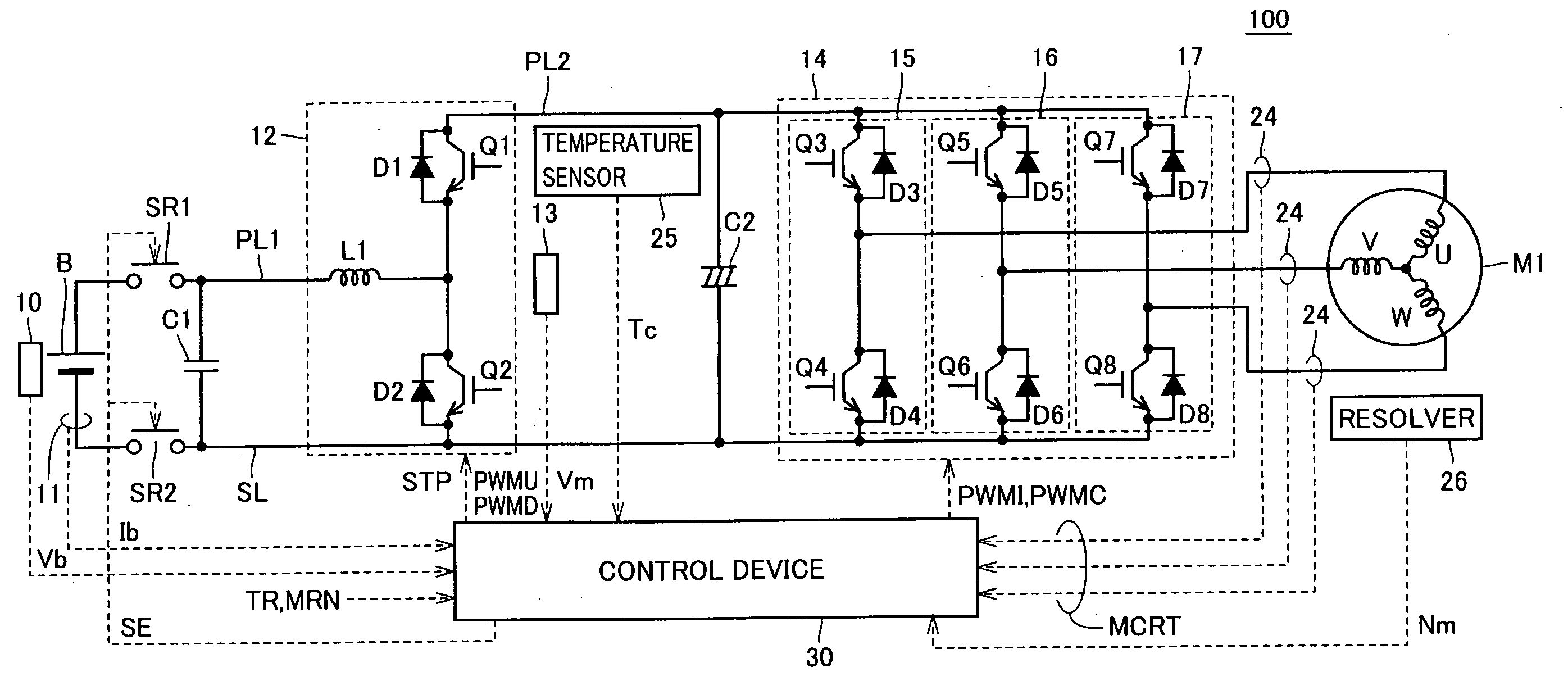
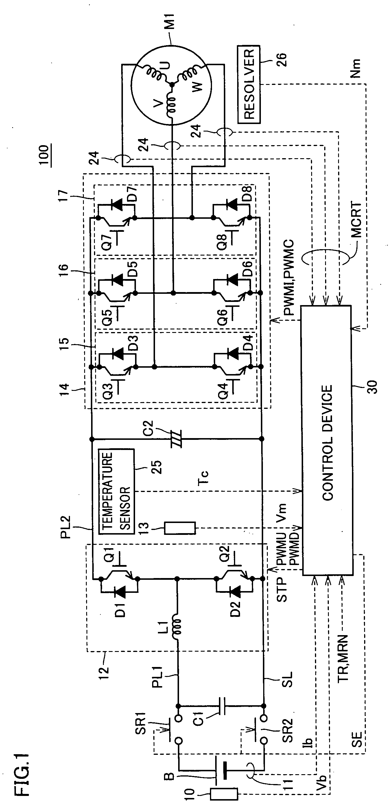
[0031]FIG. 1 is a circuit diagram of a motor drive device provided with a control device of a boost converter according to an embodiment of the present invention.

[0032]Referring to FIG. 1, a motor drive device 100 includes a DC power supply B, voltage sensors 10 and 13, system relays SR1 and SR2, capacitors C1 and C2, a boost converter 12, an inverter 14, current sensors 11 and 24, a temperature sensor 25, a resolver 26, and a control device 30. An AC motor M1 is a drive motor for generating a torque for driving a driving wheel of a hybrid vehicle or an electric vehicle. Alternatively, this motor may be incorporated in the hybrid vehicle such that it can function as a generator driven by the engine, and that it ca...


PUM


Abstract

A boost converter boosts a DC voltage of a DC power supply. An inverter converts the output voltage of the boost converter into an AC voltage. An AC motor is driven by the output voltage of the inverter. A control device which controls the boost converter reduces an output voltage instruction value of the boost converter in the case where the rotation speed of the AC motor is decreased and an absolute value of a variation rate of the rotation speed is not less than a predetermined value. The inverter is controlled in the control mode selected from a plurality of control modes including three modes of a sine wave PWM control mode, an overmodulation PWM control mode and a rectangular wave control mode. The control device of the boost converter reduces the output voltage instruction value of the boost converter only in the case where the control mode of the inverter is the rectangular wave control mode or the overmodulation control mode.

Description

TECHNICAL FIELD[0001]The present invention relates to a control device of a boost converter which converts a direct-current (DC) voltage from a DC power supply into a target voltage and a control method of the boost converter.BACKGROUND ART[0002]Considerable attention has been recently focused on a hybrid vehicle and an electric vehicle as an environmentally friendly vehicle.[0003]This hybrid vehicle uses, in addition to the conventional engine, a DC power supply, an inverter, and a motor driven by the inverter as a power source. That is, while the hybrid vehicle is powered by driving the engine, it is also powered by converting the DC voltage from the DC power supply into an alternating current (AC) voltage by the inverter and by using the converted AC voltage to rotate the motor. The electric vehicle also uses a DC power supply, an inverter, and a motor driven by the inverter as a power source.[0004]Japanese Patent Laying-Open No. 2001-295676 discloses that, in a hybrid vehicle, a...

Claims


Application Information

Patent Timeline
Patent Type & Authority Applications(United States)
IPC IPC(8): H02P27/08H02M7/5395H02M3/155B60K6/445B60L9/18B60W10/08B60W20/00H02M7/48H02P27/06
CPCH02M7/53875H02M7/5395H02P2201/09H02P27/08H02M2001/007H02M1/007H02M7/5387H02P27/06
Inventor OCHIAI, KIYOEOKAMURA, MASAKIOYANAGI, HIROYUKI
Owner DENSO CORP
Why Eureka
Try Eureka