SEPARATION, PURIFICATION AND RECOVERY METHOD OF SF6, HFCs AND PFCs

a technology of sf6, hfcs or pfcs, applied in the direction of separation processes, sulfur compounds, sulfur and halogen compounds, etc., can solve the problems of a lot of energy, and achieve the effects of reducing energy consumption, reducing emission, and effectively coping

Inactive Publication Date: 2009-05-07
YS CO LTD
View PDF13 Cites 5 Cited by
  • Summary
  • Abstract
  • Description
  • Claims
  • Application Information

AI Technical Summary

Benefits of technology

[0009]Since fluoro-gases can be concentrated 100 times intensively by using a hydrate formation method and then can be separated in a gas hydrate state, it is possible to significantly reduce the consumption of energy as compared to a conventional representative liquification method for thereby more effectively coping with an international environment regulation by reducing the emission of Non-CO2 greenhouse gas of SF6, HFCs or PFCs which has about 24,000 times higher earth warming index as compared to CO2.

Problems solved by technology
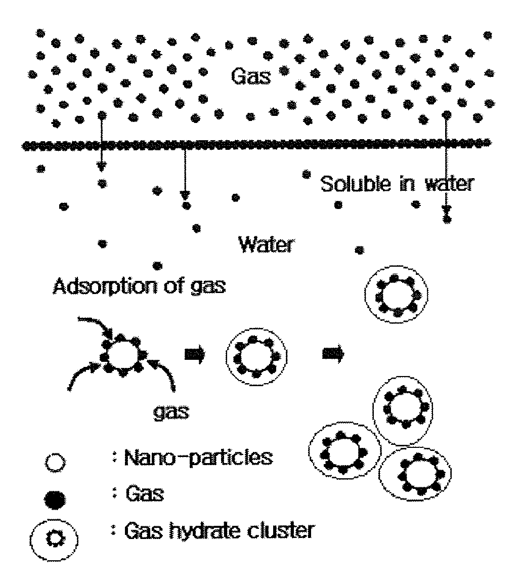
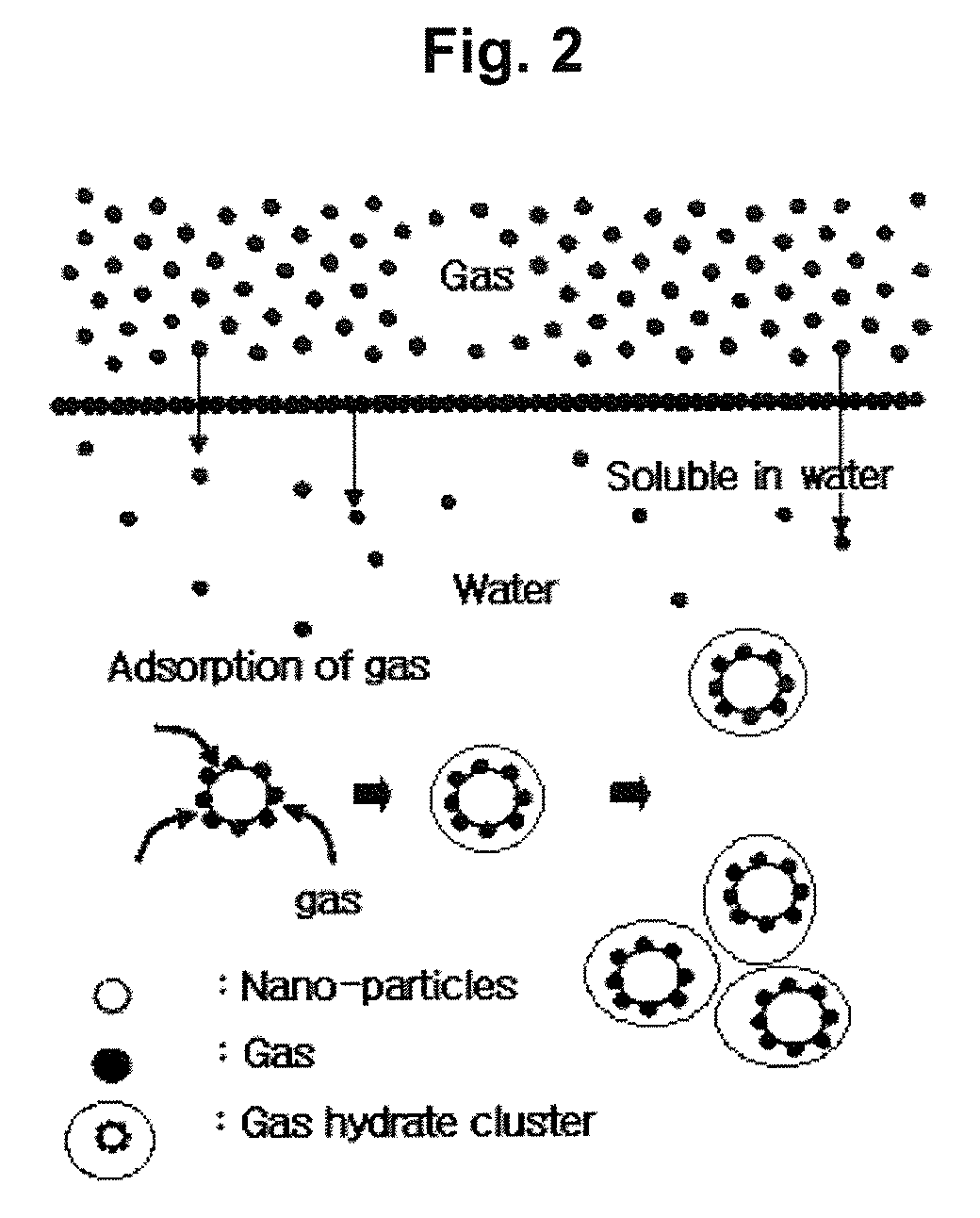
Since the liquification temperatures of gases are very low, there are a lot of difficulties for liquification, and a lot of energy is needed.

Method used


Image

  • SEPARATION, PURIFICATION AND RECOVERY METHOD OF SF6, HFCs AND PFCs
  • SEPARATION, PURIFICATION AND RECOVERY METHOD OF SF6, HFCs AND PFCs
  • SEPARATION, PURIFICATION AND RECOVERY METHOD OF SF6, HFCs AND PFCs

Examples


embodiment 1

Separation, Purification and Recovery Ratio Experiment of SF6 and Mixed Gas

[0026]Pure water(HPLC grade, 99.999%) of 125 ml is injected into a reactor, and the interior of the reactor is purged a few times by using a SF6 50%(N2 Balance) gas. The hydrate is formed at a pressure of 7.8 bar, a temperature of 276K, and an agitating speed of 500 rpm. The reactor is substantially cooled to a low temperature after the hydrate formation reaction is completed, and SF6+N2 gas, which is not changed to hydrate, is discharged from the interior of the reactor to the outside. The interior of the reactor containing only hydrate is set at a pressure of 7 bar and a temperature of 293 K, so the hydrate is dissociated. The Quantitative and Qualitative Analysis is performed using GC((Varian CP3800 Gas Chromatograph, TCD) with respect to the dissociated gas. FIGS. 3 and 4 show a result of the above experiment, respectively.

embodiment 2

Effect Comparison Experiment by Promoter

[0027]Pure water(HPLC grade, 99.999%) of 125 ml is injected into a reactor, and the interior of the reactor is purged using SF6 of 99.99%, and the hydrate formation speed is analyzed by setting a pressure of 7.8 bar and a temperature of 276K. FIG. 5 shows a result of the above experiment.

embodiment 3

Effect Experiment of LABS Promoter

[0028]Aqueous solution including Linear Alkyl Benzene Sulfonate, LABS, Aldrich is prepared depending on concentrations and is substantially mixed and melt in water. 125 ml of LABS aqueous solution prepared by concentrations is injected into the reactor same as the embodiment 2, and the interior of the reactor is purged using SF6 of 99.9%, and the SF6 hydrate formation speed is analyzed based on the time by setting a pressure of 7.8 bar and a temperature of 276K. FIG. 5 shows a result of the above experiment.

[0029]As shown in FIGS. 3 and 4, as a result of the analysis of gas obtained through a hydrate formation dissociation using SF6 of 50%(N2 Balance) gas, a composition of SF6 is about 80%, and a composition of N2 is about 20%. Namely, it is known that a separation, purification and recovery of SF6 and HFCs can be performed through the experiment of the present invention.

[0030]As shown in FIG. 5, when SF6 hydrate is formed with pure water(HPLC grade...


PUM

PropertyMeasurementUnit
temperatureaaaaaaaaaa
pressureaaaaaaaaaa

Abstract

A separation, purification and recovery method of SF6, HFCs or PFCs is disclosed, which comprises a step for forming a gas hydrate including components in addition to SF6, HFCs or PFCs. It is possible to separate and recover fluoro-gas at a much lower cost as compared to a conventional method for thereby obtaining an economical effect and preventing an emission of SF6, HFCs or PFCs which corresponds to Non-CO2 having a higher earth warming index, which leads to preventing an earth warming phenomenon. So, the present invention might be widely applied.

Description

TECHNICAL FIELD[0001]The present invention relates to a separation, purification and recovery method of SF6, HFCs or PFCs, and in particular to a separation, purification and recovery method of SF6, HFCs or PFCs through a solid / liquid separation after an intensive concentration in a gas hydrate state by reacting a gas such as SF6, HFCs or PFCs with water.BACKGROUND ART[0002]SF6, HFCs or PFCs is known to have a higher earth warming index and a longer life span and is designated as six representative earth warming gases along with CO2, CH4 and N2O. In particular, SF6 has the highest earth warming impact level among six representative earth warming gases and has 23,900 times higher earth warming index as compared to CO2 which is one of representative earth warming gases. So, SF6 is the worst environment pollutant.[0003]In addition, all countries including advanced countries as well as developing countries are included in the group for greenhouse gas emission cut countries after 2013 in...

Claims


Application Information

Patent Timeline
Patent Type & Authority Applications(United States)
IPC IPC(8): B01D53/02B01D47/00
CPCB01D53/1418B01D53/1493B01D53/70Y02C20/30B01D2257/2066Y02C20/20B01D2257/204
Inventor LEE, GANG WOOLEE, JAE JEONGMOON, DONG HYUNKIM, MIN CHOULSEOK, MIN GWANGKO, JU HYUNSHIN, HYUNG JOONKIM, YOUNG SEOGLEE, JU DONGLEE, MAN SIG
Owner YS CO LTD
Why Eureka
Try Eureka