Rapid Mounting System for Solar Modules

a solar module and mounting system technology, applied in the field of photovoltaic devices, can solve the problems of limiting the ability to install large numbers of solar panels in a cost-effective manner, affecting the ability of installers to quickly and cost-efficiently deploy solar modules at a large scale, and traditional solar module packaging comes with a great deal of redundancy and excess equipment cost, so as to reduce manufacturing costs and reduce redundant parts

Inactive Publication Date: 2009-05-07
STANCEL ROBERT
View PDF8 Cites 74 Cited by
  • Summary
  • Abstract
  • Description
  • Claims
  • Application Information

AI Technical Summary

Benefits of technology

[0006]Embodiments of the present invention address at least some of the drawbacks set forth above. The present invention provides for the improved solar module designs that reduce manufacturing costs and redundant parts in each module. These improved module designs are well suited for rapid installation. It should be understood that at least some embodiments of the present invention may be applicable to any type of solar cell, whether they are rigid or flexible in nature or the type of material used in the absorber layer. Embodiments of the present invention may be adaptable for roll-to-roll and / or batch manufacturing processes. At least some of these and other objectives described herein will be met by various embodiments of the present invention.

Problems solved by technology

Drawbacks associated with traditional solar module package designs, however, have limited the ability to install large numbers of solar panels in a cost-effective manner.
Traditional solar module packaging comes with a great deal of redundancy and excess equipment cost.
These traditional module designs inherit a large number of legacy parts that hamper the ability of installers to rapidly and cost-efficiently deploy solar modules at a large scale.
Although subsidies and incentives have created some large solar-based electric power installations, the potential for greater numbers of these large solar-based electric power installations has not been fully realized.

Method used


Image

  • Rapid Mounting System for Solar Modules
  • Rapid Mounting System for Solar Modules
  • Rapid Mounting System for Solar Modules

Examples


Embodiment Construction

[0027]It is to be understood that both the foregoing general description and the following detailed description are exemplary and explanatory only and are not restrictive of the invention, as claimed. It may be noted that, as used in the specification and the appended claims, the singular forms “a”, “an” and “the” include plural referents unless the context clearly dictates otherwise. Thus, for example, reference to “a material” may include mixtures of materials, reference to “a compound” may include multiple compounds, and the like. References cited herein are hereby incorporated by reference in their entirety, except to the extent that they conflict with teachings explicitly set forth in this specification.

[0028]In this specification and in the claims which follow, reference will be made to a number of terms which shall be defined to have the following meanings:

[0029]“Optional” or “optionally” means that the subsequently described circumstance may or may not occur, so that the des...


PUM

PropertyMeasurementUnit
total thicknessaaaaaaaaaa
thicknessaaaaaaaaaa

Abstract

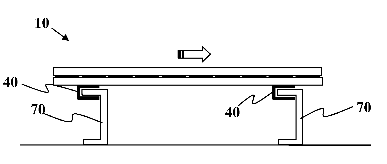
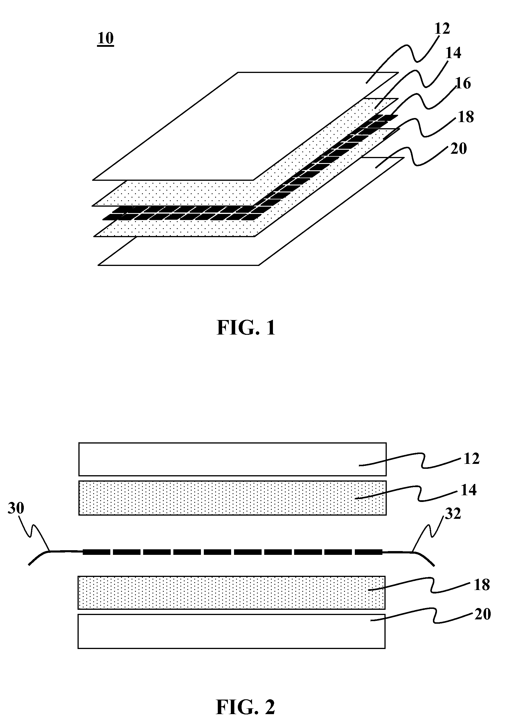
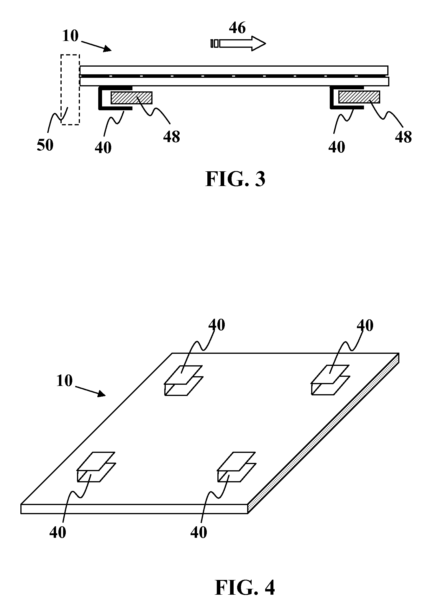
Methods and devices are provided for rapid solar module installation. In one embodiment, a photovoltaic module is provided comprising of a plurality of photovoltaic cells positioned between a transparent module layer and a backside module layer. The module may be a frameless module. The module may have brackets that slidably engage a mounting structure.

Description

CROSS-REFERENCE TO RELATED APPLICATION[0001]This application claims the benefit of priority to U.S. Provisional Application Ser. No. 60 / 950,986 filed Jul. 20, 2007. This application is fully incorporated herein by reference for all purposes.FIELD OF THE INVENTION[0002]This invention relates generally to photovoltaic devices, and more specifically, to solar cells and / or solar cell modules designed for large-scale electric power generating installations.BACKGROUND OF THE INVENTION[0003]Solar cells and solar cell modules convert sunlight into electricity. Traditional solar cell modules are typically comprised of polycrystalline and / or monocrystalline silicon solar cells mounted on a support with a rigid glass top layer to provide environmental and structural protection to the underlying silicon based cells. This package is then typically mounted in a rigid aluminum or metal frame that supports the glass and provides attachment points for securing the solar module to the installation si...

Claims


Application Information

Patent Timeline
Patent Type & Authority Applications(United States)
IPC IPC(8): H01L31/048
CPCF24J2/5247F24J2/5254F24J2002/5284F24J2002/5298Y02B10/12Y10T29/49826Y02E10/47H02S20/00H02S20/23Y10T29/49355Y02E10/50F24S25/632F24S2025/016F24S2025/023F24S25/613Y02B10/10
Inventor STANCEL, ROBERT
Owner STANCEL ROBERT
Why Eureka
Try Eureka