Spiral inductor

a spiral inductor and inductance technology, applied in the field of spiral inductors, can solve the problems of reducing the quality factor (q value), negatively affecting the performance of the inductor b>5/, etc., and achieve the effect of improving the quality factor of the inductors and improving the performance of the inductors

Active Publication Date: 2009-05-07
VIA TECH INC
View PDF21 Cites 37 Cited by
  • Summary
  • Abstract
  • Description
  • Claims
  • Application Information

AI Technical Summary

Benefits of technology

[0006]Embodiments of the invention provide spiral inductors that prevent or reduce non-uniform current density in the inductors to improve the performance of the inductors and increase the quality factor of the inductors.

Problems solved by technology

That is, the current that is flowing concentrates at the inner part of the innermost turn 6, and the effective cross-section for the current flow slashes, negatively affecting the performance of the inductor 5 and reducing the quality factor (Q value) thereof.

Method used


Image

  • Spiral inductor
  • Spiral inductor
  • Spiral inductor

Examples


Embodiment Construction

[0019]The following description is of the best-contemplated mode of carrying out the invention. This description is made for the purpose of illustrating the general principles of the invention and should not be taken in a limiting sense. The scope of the invention is best determined by reference to the appended claims.

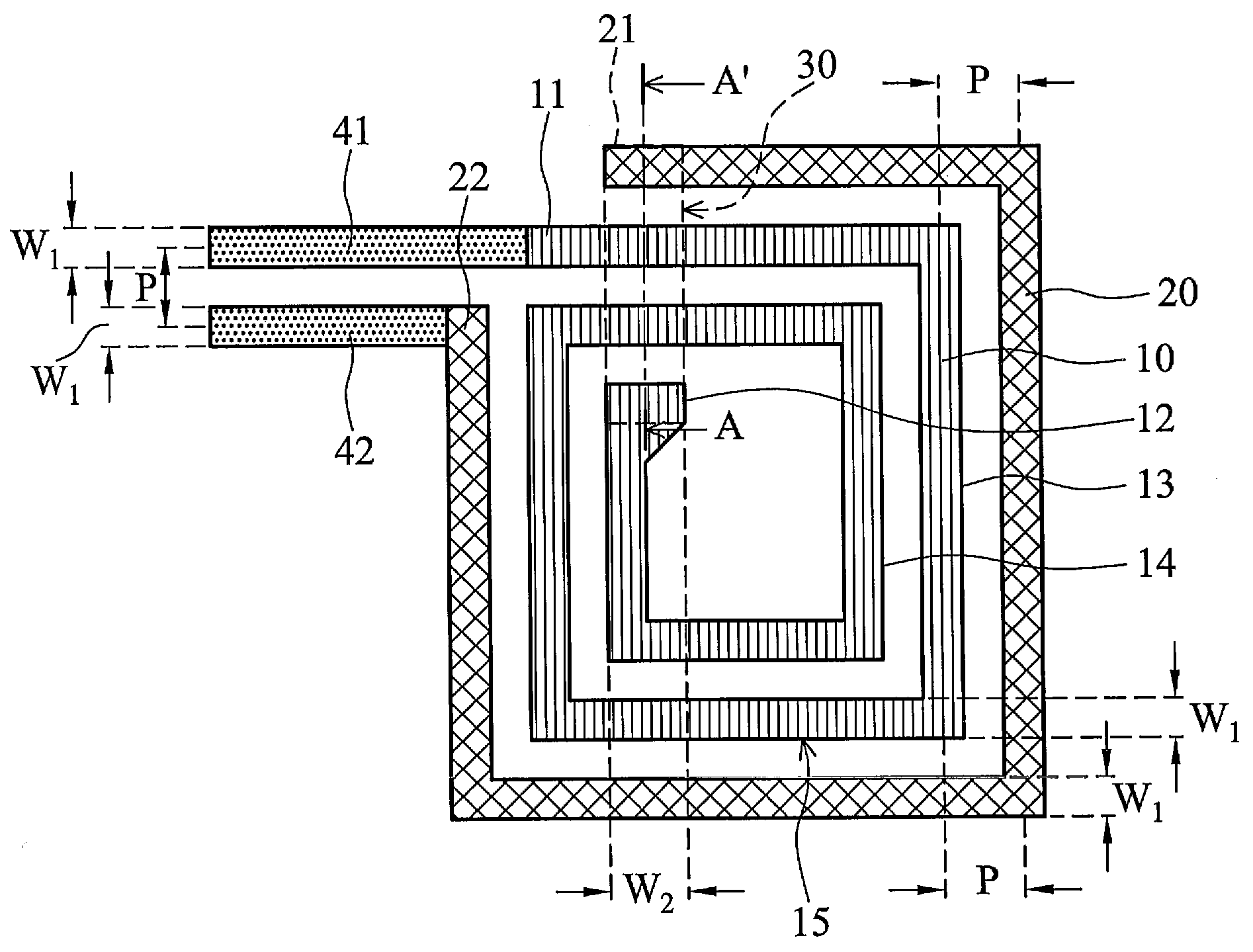
[0020]In the subsequent description, phrases such as “substantially uniform”, “substantially parallel with”, “substantially equal”, and “substantially the same” etc . . . means expected to be uniform, parallel with, equal, and the same etc. in design, as in practice, it is difficult to be mathematically or geometrically uniform, parallel with, equal, and the same etc. Additionally, when deviation is in an acceptable range of a corresponding standard or specification, it is also recognized to be uniform, parallel with, equal, and the same etc. Those skilled in the art are expected to acknowledge, that different standards or specifications, depend upon various properties...


PUM

PropertyMeasurementUnit
conductiveaaaaaaaaaa
width W1aaaaaaaaaa
electricallyaaaaaaaaaa

Abstract

A spiral inductor is provided. The spiral inductor includes a first spiral conductive trace with at least one turn, a second spiral conductive trace, and a connector. The first spiral conductive trace comprises an outer end and an inner end. The second spiral conductive trace surrounds a portion of the outermost turn of the first spiral conductive trace, and comprises a first end and a second end. The connector electrically connects to the inner end and the first end.

Description

BACKGROUND OF THE INVENTION[0001]1. Field of the Invention[0002]The invention relates to an inductor and more particularly to an inductor device with multi-layered interconnections.[0003]2. Description of the Related Art[0004]As shown in FIG. 1, for a 0.35-μm silicon process, a silicon oxide layer 3 is disposed on a p-well layer 2 on a silicon substrate 1. Three metal layers M1, M2, and M3 are embedded in the silicon oxide layer 3, and the top metal layer M3 is exposed on an upper surface of the silicon oxide layer 3. A silicon nitride layer 4 covers the silicon oxide layer 3 and the metal layer M3. The metal layer M3 is the thickest of the three metal layers M1, M2, and M3, and thus, the conductivity thereof is higher than the other two metal layers. Further, the metal layer M3 also comprises a conductor loss lower than those of the other two metal layers. As a result, the metal layer M3 is suitable for RF (radio frequency) low-loss component designs.[0005]FIG. 2 is a top view of a...

Claims


Application Information

Patent Timeline
Patent Type & Authority Applications(United States)
IPC IPC(8): H01F5/00
CPCH01F17/0006H01F27/292H01F41/10H01F2017/0046H01F2017/0086H01L2924/0002H01L23/5227H01L2924/00
Inventor LEE, SHENG-YUANLIN, HSIAO-CHU
Owner VIA TECH INC
Why Eureka
Try Eureka