Display device
- Summary
- Abstract
- Description
- Claims
- Application Information
AI Technical Summary
Benefits of technology
Problems solved by technology
Method used
Image

Examples
embodiment 1
Preferred Embodiment 1
[0116]A configuration of a liquid crystal display device in accordance with preferred embodiment 1 of the present invention is mentioned below. The configuration of the liquid crystal display device of the present invention is not limited to this configuration.
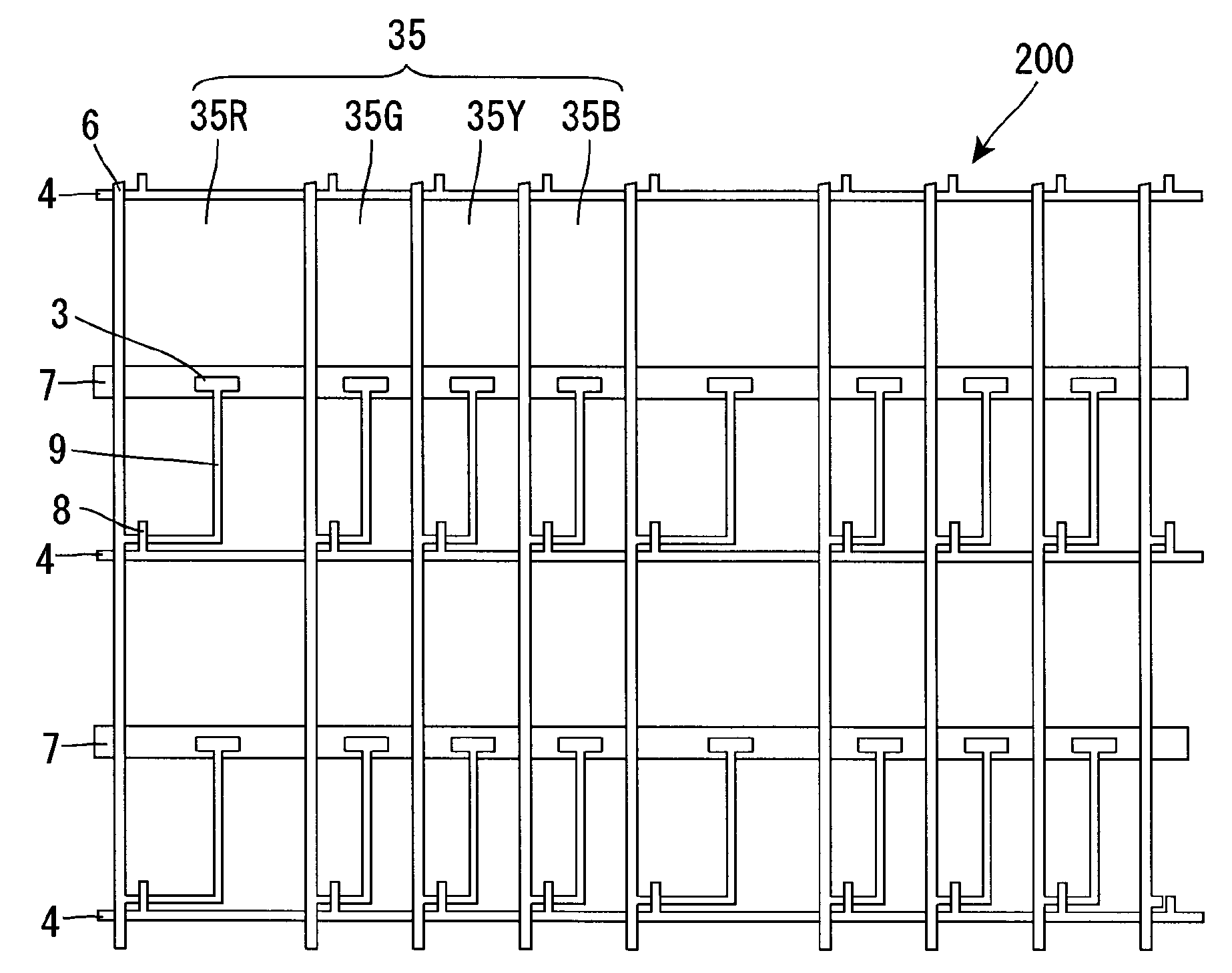
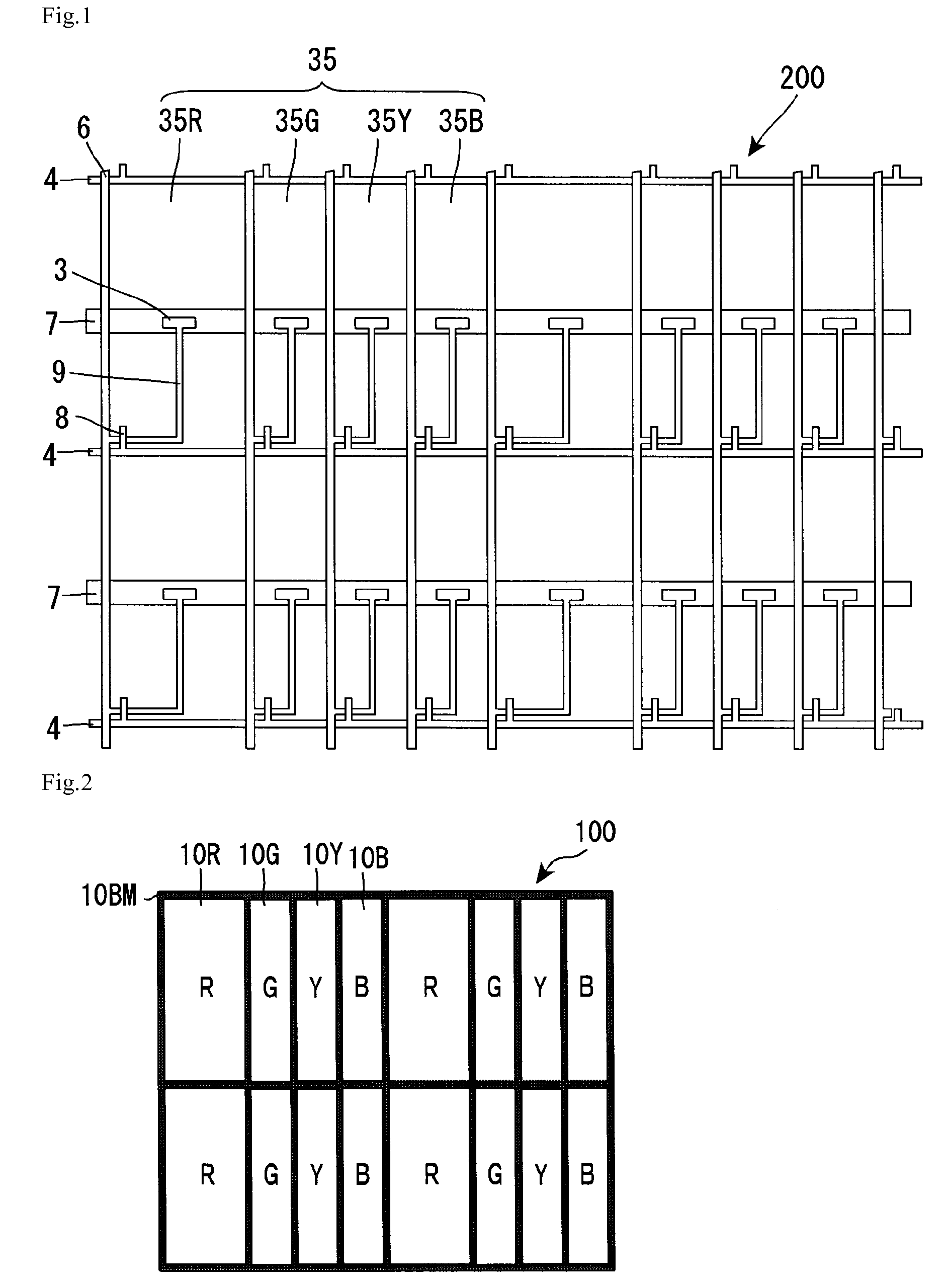
[0117]FIG. 1 is a planar view schematically showing a configuration of a TFT substrate 200 in a transmissive liquid crystal display device in accordance with preferred embodiment 1 of the present invention. As shown in FIG. 1, the TFT substrate 200 has the following configuration. Matrix wirings defined by scanning lines 4 and signal lines 6 are arranged on a glass substrate, for example. In each intersection of the matrix wirings, a thin film transistor (TFT) 8 is arranged. In each region surrounded by the matrix wirings, a transmissive electrode 35 (including transmissive electrodes 35R, 35G, 35Y, and 35B) made of a transparent conductive material such as indium tin oxide (ITO) is arranged. A gate elect...
embodiment 2
Preferred Embodiment 2
[0138]With regard to a transmittance level relationship among the respective color filters arranged in the red, green, blue, and yellow sub-pixels, and a transmittance of the color filters for displaying white (an average transmittance of the red, green, blue, and yellow sub-pixels), yellow, green, white, red, and blue are ranked in descending order of transmittance. In some cases, the red and blue are counterchanged, and yellow, green, white, blue, and red are ranked in descending order of transmittance.
[0139]Accordingly, if the aperture area of the red sub-pixel is increased, the transmittance of the color filters for displaying white is decreased because the color filter arranged in the red sub-pixel has a smaller transmittance than that of the color filters for displaying white. In addition, if the aperture areas of the green and yellow sub-pixels are decreased, the transmittance of the color filters for displaying white is further decreased because the col...
embodiment 3
Preferred Embodiment 3
[0151]As mentioned in preferred embodiment 2, the preferred embodiment in which the red sub-pixel has the largest aperture area and the green or yellow sub-pixel has the smallest aperture area is advantage in that the reduction in lightness of white can be minimized. In the present preferred embodiment, the following preferred embodiment is mentioned as a more preferable preferred embodiment: the aperture areas of the blue sub-pixel as well as the red sub-pixel are equivalently large and the aperture areas of the green and yellow sub-pixels are equivalently small.
[0152]In the present preferred embodiments, six liquid crystal display devices E1 to E6 shown in Table 7 were prepared. In each case, the aperture areas of the red and blue sub-pixels are equivalently large and the aperture areas of the green and yellow sub-pixels are equivalently small. Table 7 shows an aperture area ratio among the respective sub-pixels, an aperture area ratio between the sub-pixel h...
PUM
 Abstract
Description
Claims
Application Information
 - Generate Ideas
- Intellectual Property
- Life Sciences
- Materials
- Tech Scout
- Unparalleled Data Quality
- Higher Quality Content
- 60% Fewer Hallucinations
Browse by: Latest US Patents, China's latest patents, Technical Efficacy Thesaurus, Application Domain, Technology Topic, Popular Technical Reports.
© 2025 PatSnap. All rights reserved.Legal|Privacy policy|Modern Slavery Act Transparency Statement|Sitemap|About US| Contact US: help@patsnap.com