
Operation methods for memory cell and array for reducing punch through leakage

a memory cell and array technology, applied in the field of nonvolatile memory cell array programming, can solve the problems of long-term reliability problems of memory cells, high electric fields and punch through leakage in unselected memory cells, and achieve the effect of reducing punch through leakage and broader range of applicability

Active Publication Date: 2009-05-07
MACRONIX INT CO LTD
View PDF24 Cites 24 Cited by
  • Summary
  • Abstract
  • Description
  • Claims
  • Application Information

AI Technical Summary

Benefits of technology

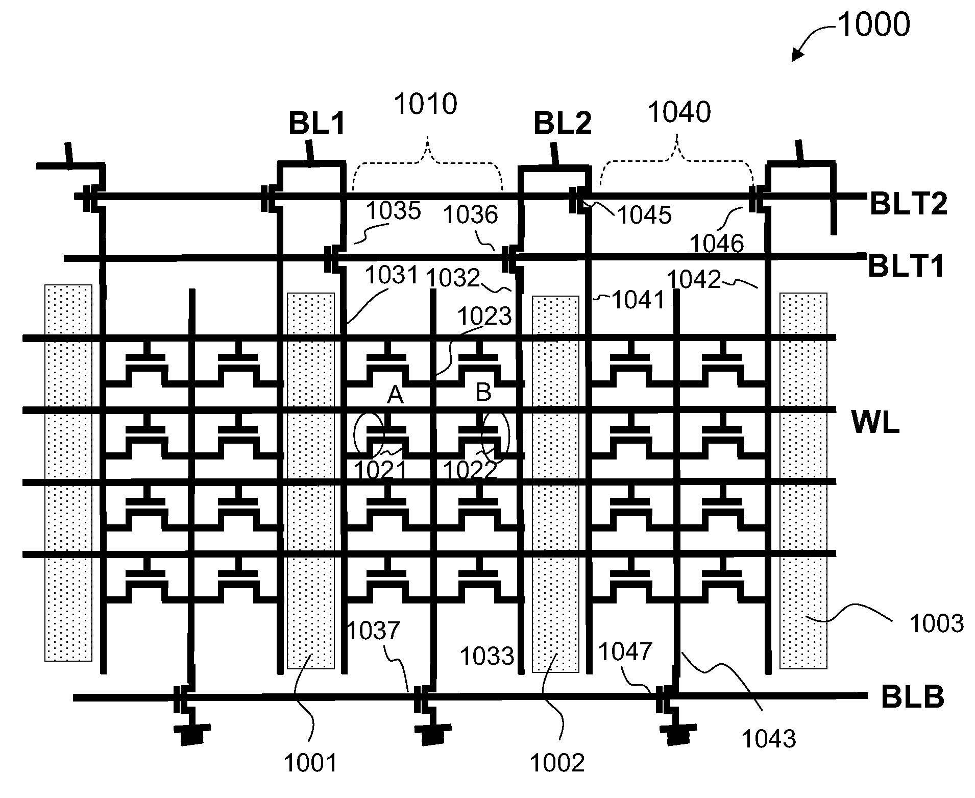
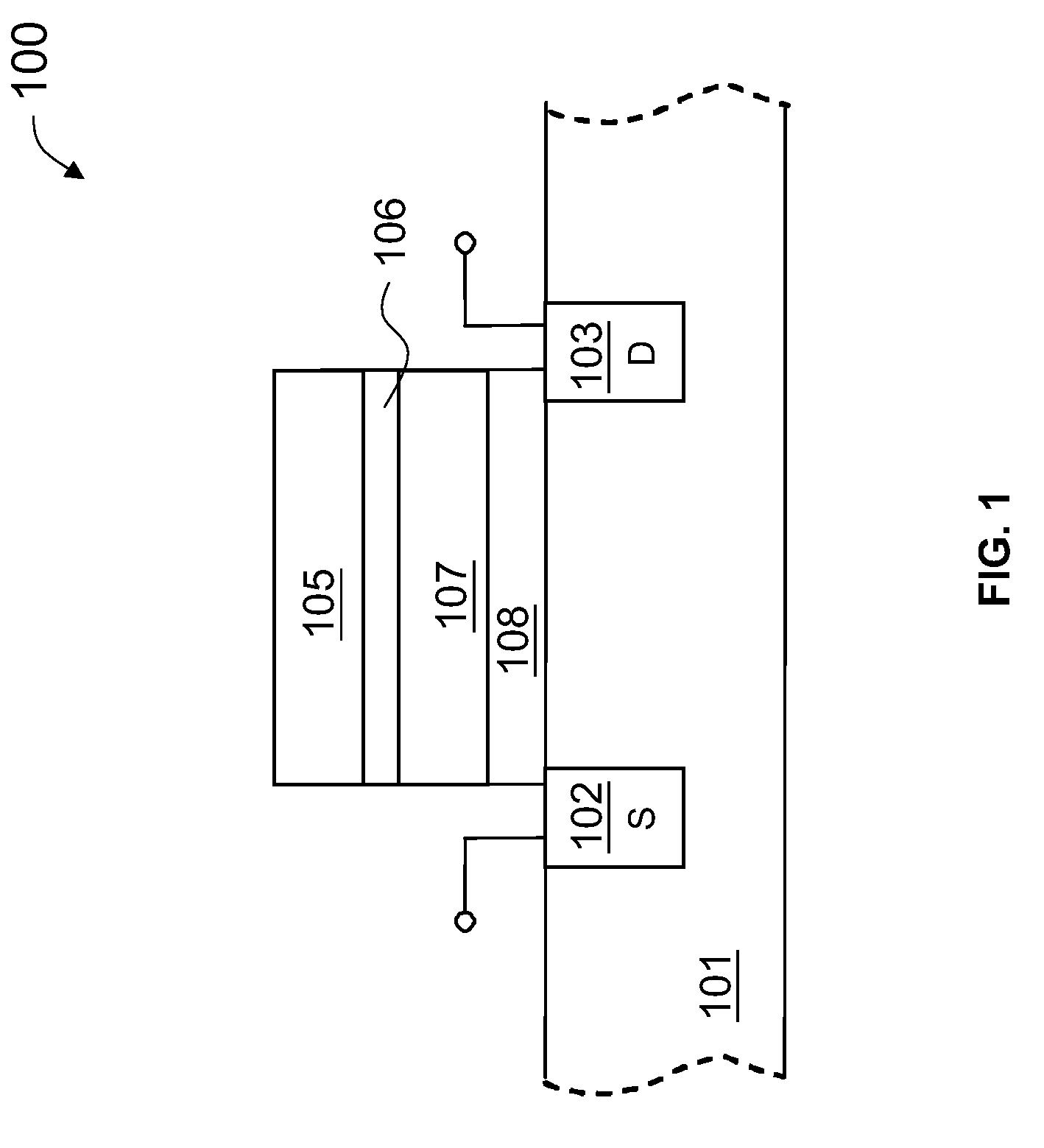
[0009]The present invention is directed to non-volatile memory cell arrays and their methods of operation. More particularly, the invention provides a method for programming a memory cell in a non-volatile memory cell array that reduces punch through leakage in unselected memory cells. Merely by way of example, the invention has been applied to certain non-volatile memory arrays including floating gate and nitride charge storage materials. But it would be recognized that the invention has a much broader range of applicability.
[0025]Many benefits are achieved by way of the present invention over conventional techniques. For example, the present technique provides an easy to use process that relies upon conventional technology. In some embodiments, the invention provides methods for operating a virtual ground non-volatile memory array that reduces punch through leakage current in the memory array. In some embodiment, the invention provides non-volatile memory arrays including various configurations of global bit lines, local bit lines, global source lines, and local source lines. In some embodiments, switch devices couple voltage sources to various bit lines and source lines. Operation methods for each array structure are also provided for reducing punch through leakage current. Additionally, the memory cells and array structures can be made using conventional process technology without substantial modifications to conventional equipment and processes. These and other benefits will be described in more detail throughout the present specification and more particularly below.

Problems solved by technology

This high voltage appears on the drain terminals of unselected memory cells and can cause high electric fields and punch through leakage in the unselected memory cells.
The leakage current can result in a high power consumption of the memory chip.
The leakage current can also lead to long term reliability problems of the memory cells.
With continued shrinkage of semiconductor devices, the problem of punch through leakage is becoming increasingly more serious.

Method used


Image

  • Operation methods for memory cell and array for reducing punch through leakage
  • Operation methods for memory cell and array for reducing punch through leakage
  • Operation methods for memory cell and array for reducing punch through leakage

Examples


Embodiment Construction

[0051]The present invention is directed to non-volatile memory cell arrays and their methods of operation. More particularly, the invention provides a method for programming a memory cell in a non-volatile memory cell array that reduces punch through leakage in unselected memory cells. Merely by way of example, the invention has been applied to certain non-volatile memory arrays including floating gate and nitride charge storage materials. But it would be recognized that the invention has a much broader range of applicability.

[0052]Various operation methods and array structures will now be discussed in one or more of the embodiments to follow. Various features in these embodiments are merely examples, which should not unduly limit the scope of the claims herein. One of ordinary skill in the art would recognize many variations, modifications, and alternatives.

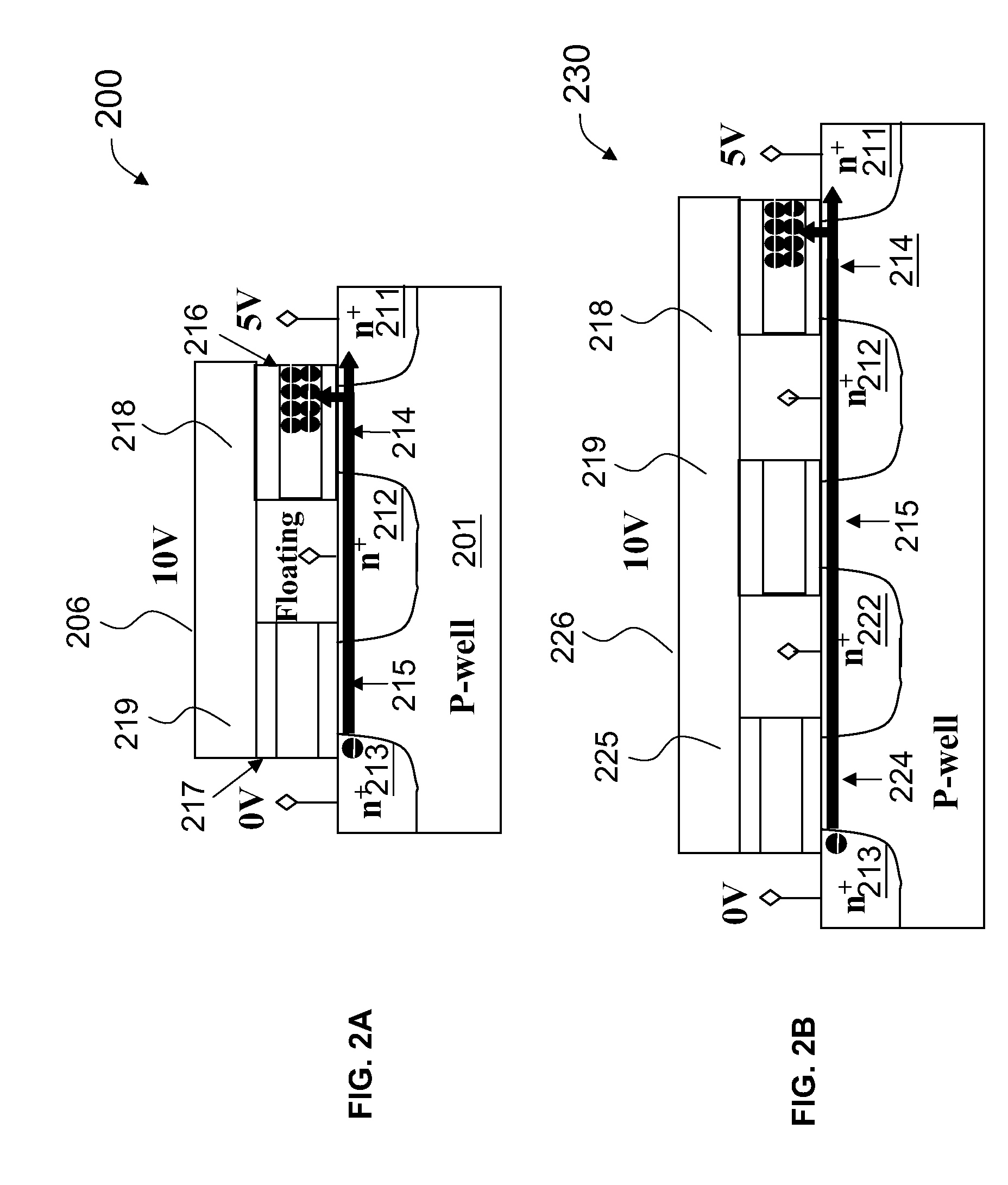
[0053]FIG. 2A is a simplified view diagram illustrating a method for programming a nonvolatile memory cell according to an emb...


PUM


Abstract

A method for programming a first memory cell in a memory array. In a specific embodiment, each memory cell has a drain, a source, a channel, and a control gate overlying a charge storage material and the channel. The source of the first memory cell is coupled to the drain of a second memory cell. A voltage is applied to the drain of the first memory cell, and the source of the second memory cell is grounded. The method includes floating the drain of the second memory cell and the source of the first memory cell and turning on the channels of the first and second memory cells, effectively forming an extended channel region. Hot carriers are injected to the charge storage material of the first cell to program the first memory cell. The extended channel lowers electrical fields and reduces punch through leakage in unselected memory cells.

Description

CROSS-REFERENCES TO RELATED APPLICATIONS[0001]This application claims benefit of priority to U.S. Provisional Application 60 / 985,966, filed Nov. 6, 2007, U.S. Provisional Application 60 / 986,960 filed Nov. 9, 2007, U.S. Provisional Application 60 / 986,198, filed Nov. 7, 2007, and U.S. Provisional Application 60 / 986,479, filed Nov. 8, 2007, commonly assigned, which are incorporated in their entirety by reference for all purpose. This application is also related to concurrently filed U.S. patent application Ser. No. ______, Attorney docket number 021265-001310US, commonly assigned and incorporated by reference herein for all purposes.BACKGROUND OF THE INVENTION[0002]The present invention is directed to non-volatile memory cell arrays and their methods of operation. More particularly, the invention provides a method for programming a memory cell in a non-volatile memory cell array that reduces punch through leakage in unselected memory cells. Merely by way of example, the invention has b...

Claims


Application Information

Patent Timeline
Patent Type & Authority Applications(United States)
IPC IPC(8): G11C11/34
CPCG11C5/04G11C16/0416H01L27/11568H01L27/11521G11C16/10H10B41/30H10B43/30
Inventor CHONG, LIT-HOTSAI, WEN-JEROU, TIEN-FANHUANG, JYUN-SIANG
Owner MACRONIX INT CO LTD
Learn More