
Method and system for opportunistic hybrid relay selection scheme for downlink transmission

Inactive Publication Date: 2009-05-07
NTT DOCOMO INC
View PDF6 Cites 40 Cited by
  • Summary
  • Abstract
  • Description
  • Claims
  • Application Information

AI Technical Summary

Benefits of technology

[0027]A scheme under the present invention trades-off overall overhead and latency inherent in relaying or cooperative communications techniques, while still offering a good outage probability and throughput performance.

Problems solved by technology

However, such a method requires considerable modifications to existing radio-frequency front-ends, which increase both the complexity and cost of the transceivers.
As a result, beamforming capability is not used in Laneman II.
Such relaying schemes are usually difficult to maintain in practice.
Apart from practical space-time coding for the cooperative relay channel, the formation of virtual antenna arrays using individual RSs distributed in space requires significant amount of coordination.
For a mobile network, location estimation is necessarily repeated frequently, resulting in substantial overhead.
Because more than one RS listens to each transmission, such relaying schemes are complex, so that an upper limit on the number of relays that should be used in any given situation is appropriate.
Furthermore, the MAC protocol layer becomes more complicated, because it is required to support relay selection.
Zhao, Tabet, Lo and Kim's methods all involve only one RS and thus do not benefit from cooperative diversity.
Yoon's scheme may introduce latency or even a deadlock between the BS and RSs, as the number of RSs increases.
Bletsas's scheme is very complex, especially in a fast-moving mobile environment.
Furthermore, fast switching among RSs increases the workload and overhead of the central controller.
Therefore, the selection of “best RS” based on instantaneous channel conditions is less appropriate for fast-moving mobile environments (e.g., outdoor environment) than for static or nomadic environments (e.g., indoor environment).
Tabet has the drawback of focusing on selecting one RS at each hop.

Method used


Image

  • Method and system for opportunistic hybrid relay selection scheme for downlink transmission
  • Method and system for opportunistic hybrid relay selection scheme for downlink transmission
  • Method and system for opportunistic hybrid relay selection scheme for downlink transmission

Examples


Embodiment Construction

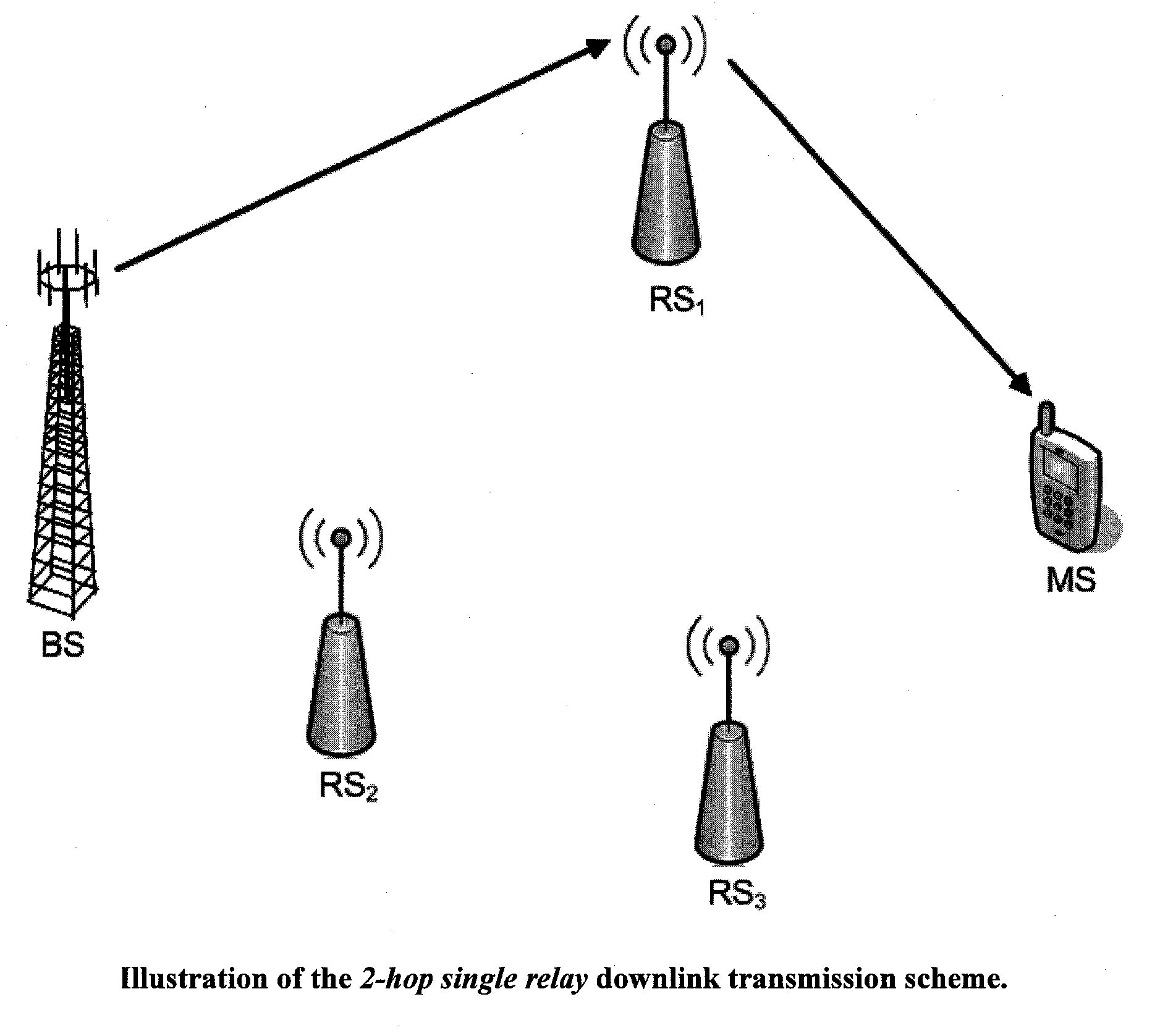
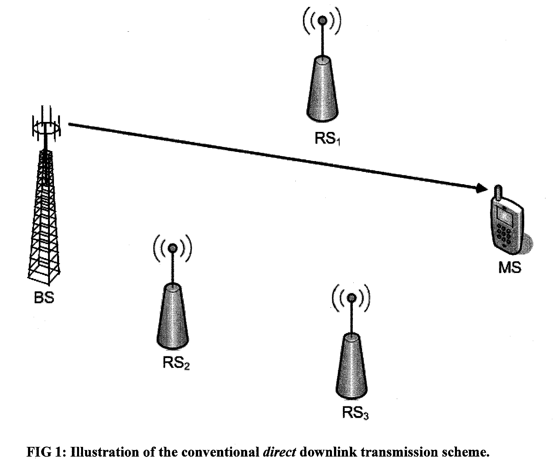
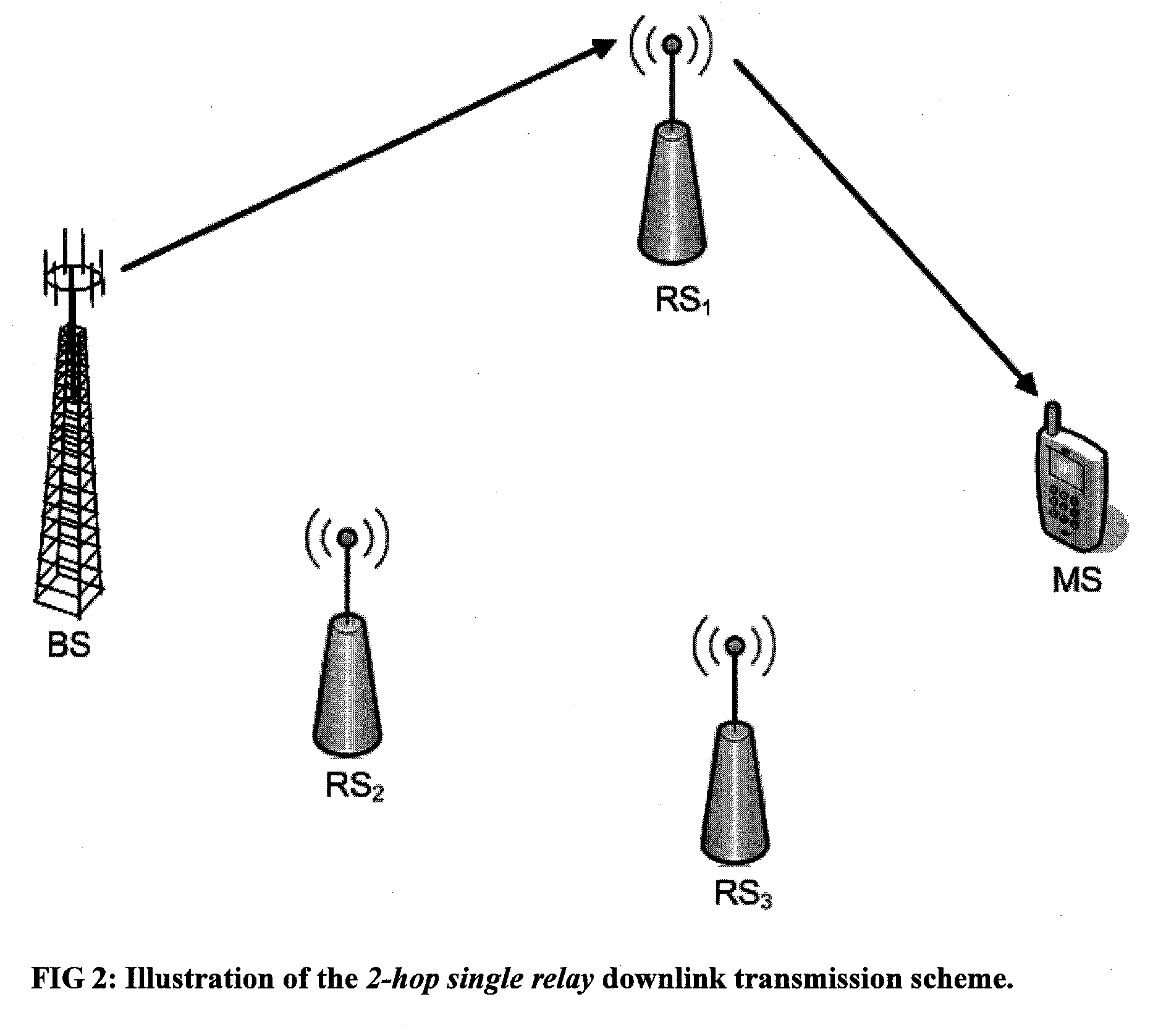
[0038]FIG. 1 illustrates a conventional direct downlink transmission scheme in a cellular network, in which a BS transmits a signal to an MS within the coverage area of the BS. Often, however, such a MS may be located in a coverage hole, or may be outside of the coverage area of the BS. If the MS is in a coverage hole or outside of the coverage area of the BS, one or more RSs may be used to carry out the desired transmission. FIG. 2 illustrates a simple 2-hop single relay downlink transmission scheme, using a single RS. FIG. 3 illustrates a multi-hop single relay downlink transmission scheme, using two or more RSs. These indirect transmission schemes are low-cost candidates that can provide the benefits of capacity enhancement and coverage extension.

[0039]FIG. 4 illustrates a cooperative relay downlink transmission scheme, in which the desired transmission arrives at the MS over both direct and indirect transmission paths. Cooperative relay, also referred to as cooperative communica...


PUM


Abstract

An opportunistic hybrid-relay selection scheme for downlink transmission selects between cooperative relay and single relay schemes based on the channel conditions (e.g., signal-to-noise-ratio (SNR)) between the base station (BS) and RSs (i.e., BS-RSs link) and RSs and mobile station (MS) (i.e., RSs-MS link), respectively. In another selection scheme, a selection between the single relay (e.g., best-relay) transmission scheme or the cooperative-relay transmission scheme may be determined based on transmission paths (e.g., line-of-sight, obstructed-light-of-sight, non-light-of-sight) and channel conditions (e.g., SNR) between the BS-RSs link and the RSs-MS link, respectively.

Description

CROSS REFERENCE TO RELATED APPLICATIONS[0001]The present application relates to and claims priority of U.S. provisional application (“Copending Provisional Application”), Ser. No. 60 / 985,175, entitled “Method and System for Opportunistic Hybrid Relay Selection Scheme for Downlink Transmission,” by C. Chong et al., filed on Nov. 2, 2007.[0002]The present application is also related to U.S. provisional patent applications, (a) Ser. No. 60 / 947,153, entitled “Method and System for Reliable Relay-Associated Transmission Scheme” (“Wang I”), naming as inventors D. Wang, C. C. Chong, I. Guvenc and F. Watanabe, filed on Jun. 29, 2007; and (b) Ser. No. 60 / 951,532, entitled “Method and System for Opportunistic Cooperative Transmission Scheme” (“Wang II”), naming as inventors D. Wang, C. C. Chong, I. Guvenc and F. Watanabe, filed on Jul. 24, 2007.[0003]The present invention is also related to U.S. Patent Application (“Copending Non-provisional Application”), entitled “Method and System for Reli...

Claims


Application Information

Patent Timeline
IPC IPC(8): H04B7/14
CPCH04B7/15592H04B7/026
Inventor CHONG, CHIA-CHINWATANABE, FUJIOINAMURA, HIROSHI
Owner NTT DOCOMO INC
Learn More