Fuel cell system

Inactive Publication Date: 2009-05-07
NEC CORP
View PDF3 Cites 5 Cited by
  • Summary
  • Abstract
  • Description
  • Claims
  • Application Information

AI Technical Summary

Benefits of technology

[0028]According to the present invention, the fuel cell system is provided to able to make the power generation environment of the MEA uniform, after reducing a space required by a portable apparatus and achieving low power consu

Problems solved by technology

However, the (B) structure of the natural intake type in which the surface of the cathode is exposed to the atmosphere cannot generate power when the surface of the cathode is coated.
Therefore, a structure of housing the fuel cell system in the potable device is difficult to be employed.
However, in the fuel cell system consuming large power, the air has to pass through many fuel cells in a process of airflow through a space between the fuel cell stack and the housi

Method used


Image

  • Fuel cell system
  • Fuel cell system
  • Fuel cell system

Examples


first exemplary embodiment

(Configuration)

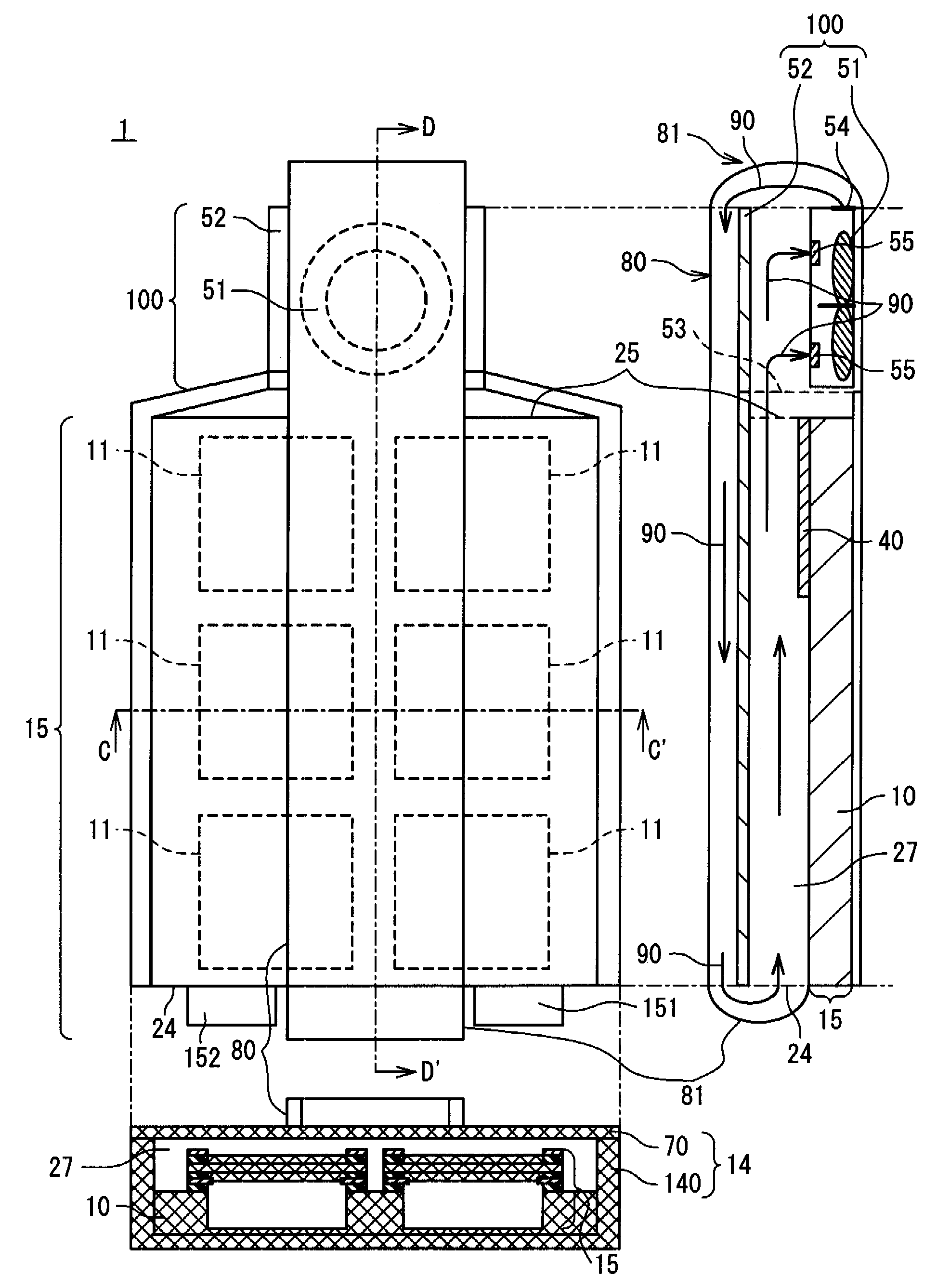
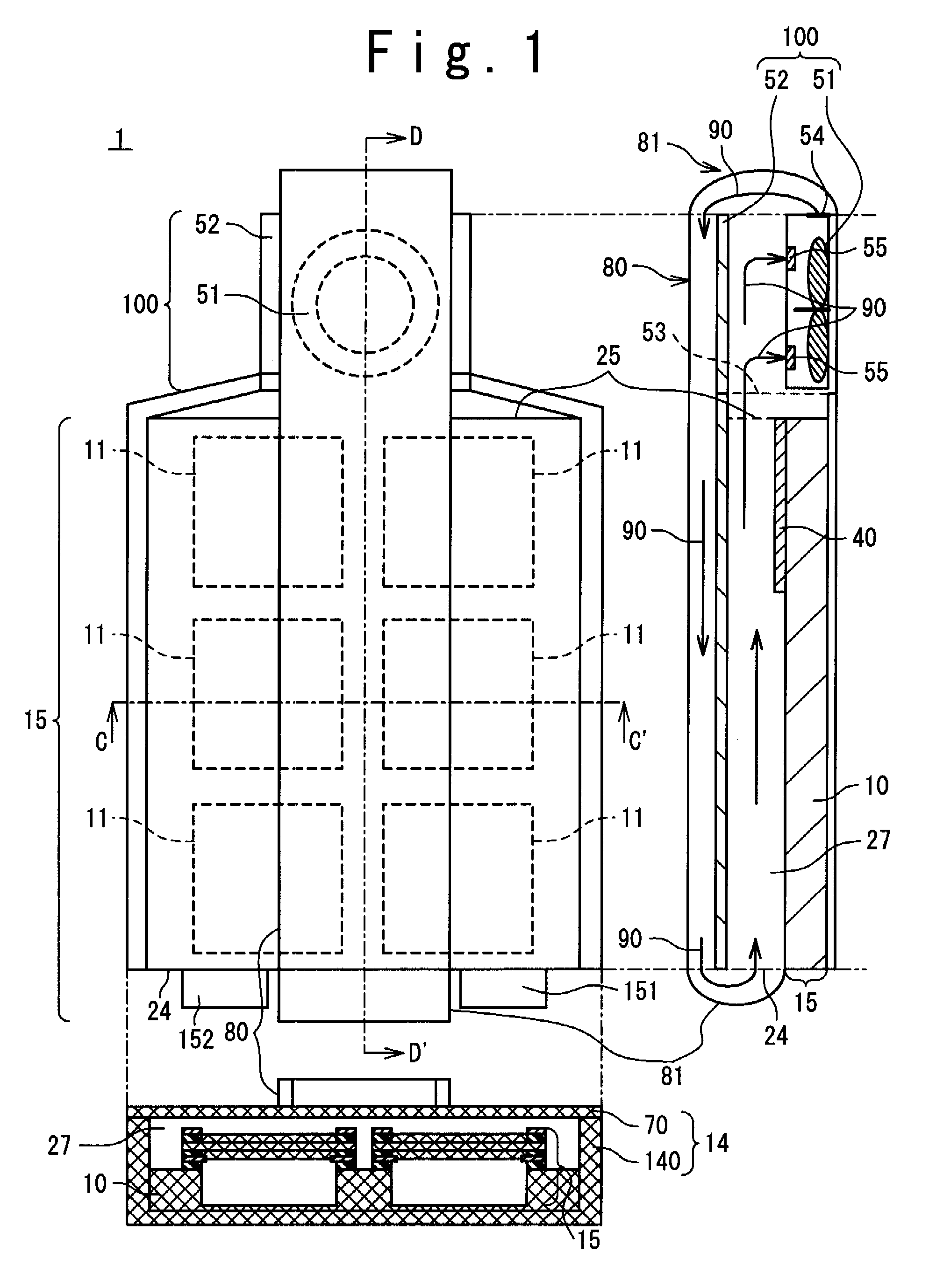
[0048]FIG. 1 is a schematic diagram showing a structure of a fuel cell system 1 according to a first exemplary embodiment of the present invention. In FIG. 1, a top view of a fuel cell stack 15, a sectional view along a DD′ line of the top view, and a sectional view along a CC′ line are shown. In the top view, although an internal configuration cannot be seen actually since it is covered with a housing and a duct, the internal configuration is shown visibly for simplification of description.

[0049]The fuel cell system 1 includes a fuel cell stack 15 in which a plurality of fuel cells 11 are arranged on a frame 10 on a plane, a housing 14 for housing the fuel cell stack 15, an airflow generating section 100 for forming airflow, and a duct 80. A space (an airflow space 27) is provided between the fuel cell stack 15 and the housing 14. The airflow space 27 communicates with the airflow generating section 100 at one end 25 and communicates with an inside of the duct 80 at ...

second exemplary embodiment

[0091]Next, the fuel cell system 1 according to a second exemplary embodiment of the present invention will be described. FIG. 9 is a diagram showing a configuration of the fuel cell system 1 according to the present exemplary embodiment. Compared to the first exemplary embodiment, the second exemplary embodiment is different from the first exemplary embodiment in that the duct 80 is not provided and that a partition 26 is provided in the airflow space 27. A configuration of the fuel cell 11 is the same as that of the first exemplary embodiment and its explanation will be omitted.

[0092]The partition 26 is installed to divide columns of the fuel cells 11 arranged in a matrix of 2 columns×3 rows. By the partition 26, the airflow space 27 is divided into a first airflow space 27A and a second airflow space 27B.

[0093]The partition 26 is formed of a material able to make a flow of the air uniform. That is, an air flow is divided by the partition 26 in the first airflow space 27A and the ...

first example

[0103]A fuel cell system used in a first example has a configuration shown in FIG. 1. A structure of the fuel cell will be described below. At first, catalyst-carrying carbon fine particles which hold platinum fine particles with the particle diameter within a range from 3 to 5 nm at 50% ratio by weight on carbon particles (ketjen black EC600JD manufactured by LION Co.) was prepared. By adding Nafion solution (name of commodity; DE521, the “Nafion” is a registered trade mark of Dupont Co.) of 5% by weight into the catalyst-carrying carbon fine particles of 1 g and agitating the solution, catalyst paste for forming a cathode was obtained. By coating the catalyst paste on carbon paper (TGP-H-120 manufactured by Toray Co.) as a substrate in a coating amount from 1 to 8 mg / cm2 and drying it, the cathode 31 of 4 cm×4 cm was manufactured. On the other hand, a catalyst paste for forming an anode was obtained under a same condition as in obtaining the catalyst paste for forming the above-me...


PUM


Abstract

The present invention makes a power generation environment of a MEA uniform. A fuel cell system of the present invention includes a fuel cell stack having a plurality of fuel cells arranged on an identical plane, a housing configured to cover the fuel cell stack above a surface of said fuel cell stack through an airflow space, an airflow generating section configured to form airflow in said airflow space, and a blowing path provided such that exhaust gas exhausted from the airflow space is introduced into the airflow space again via the airflow generating section.

Description

TECHNICAL FIELD[0001]The present invention relates to a fuel cell system, and especially relates to a planar stack type fuel cell system in which a plurality of fuel cells are arranged on an identical plane.BACKGROUND ART[0002]A polymer electrolyte fuel cell includes a Membrane and Electrode Assembly (hereinafter to be referred to as MEA) having a structure in which a polymer electrolyte membrane is held between an anode and a cathode. A fuel cell of a type of directly supplying liquid fuel to the anode is referred to as a direct type fuel cell. In a power generation mechanism, the supplied liquid fuel is decomposed on catalyzer supported by the anode so as to generate protons, electrons, and intermediate products. Generated cations passes through the solid polymer electrolyte membrane to a cathode side and the generated electrons move to the cathode side through an external load. The power generation is performed while producing a reaction product through the reaction of the proton...

Claims


Application Information

Patent Timeline
IPC IPC(8): H01M2/12H01M2/02
CPCH01M8/04097H01M8/04201H01M8/1011Y02E60/50H01M8/2475H01M2008/1095H01M8/241H01M8/2418H01M8/2484H01M8/242
Inventor SEKINO, SHOJI
Owner NEC CORP
Why Eureka
Try Eureka