

RF power amplifier controlled by estimated distortion level of output signal of power amplifier
- Summary
- Abstract
- Description
- Claims
- Application Information
AI Technical Summary
Benefits of technology
Problems solved by technology
Method used
Image

Examples
first embodiment
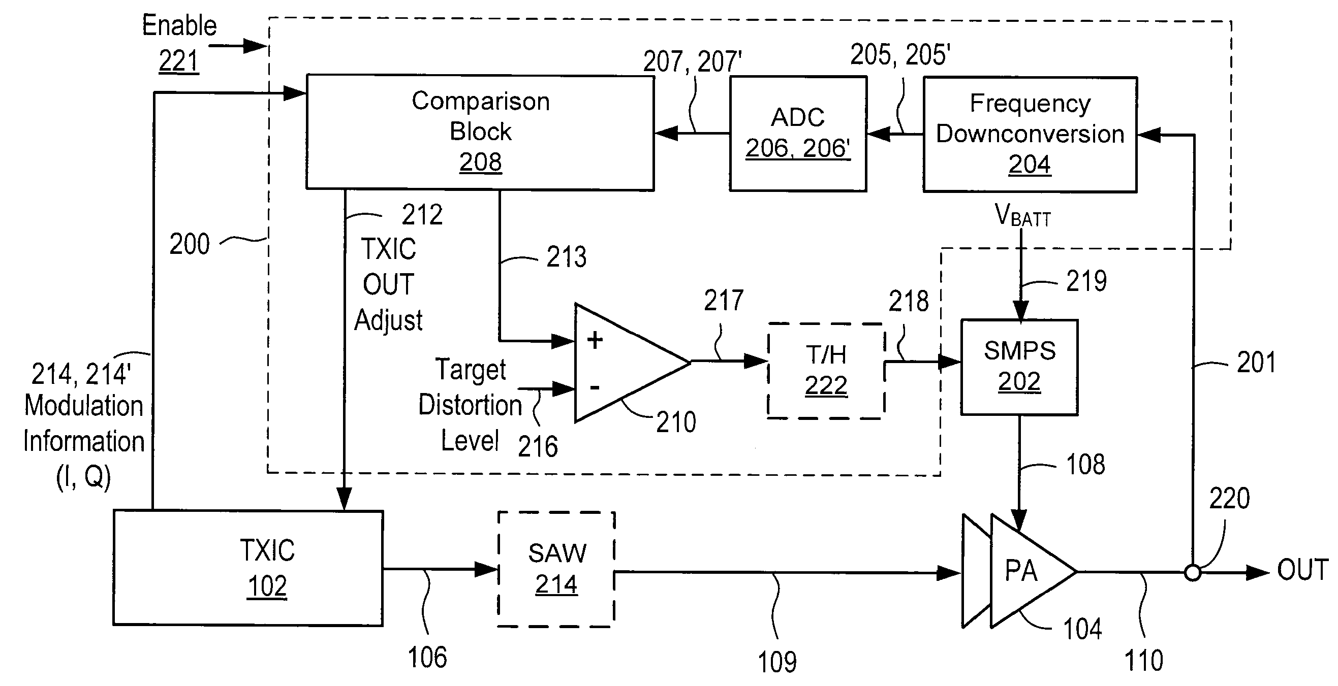
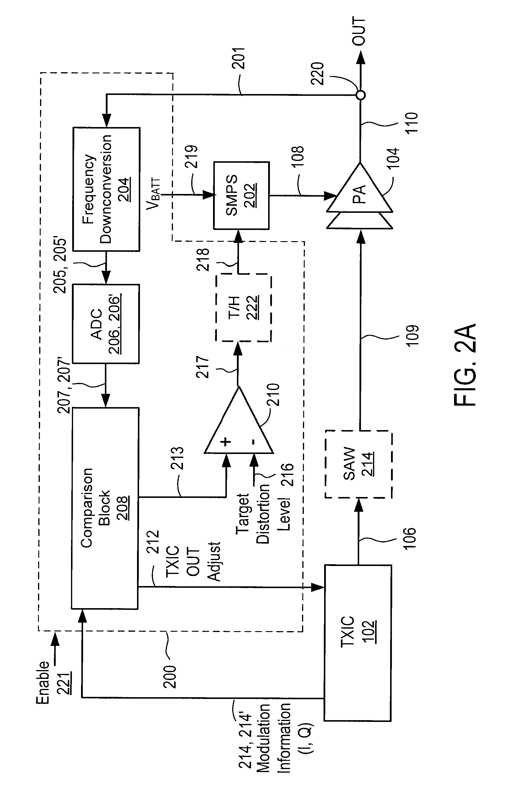
[0036]FIG. 2A illustrates an RF PA system that includes a PA controller for adjusting the supply voltage to the power amplifier based upon an estimated distortion level of the output of the PA compared to a target distortion level, according to the present invention. The RF PA system of FIG. 2A comprises, among other components, a power amplifier (PA) 104, a power supply (e.g., switched mode power supply (SMPS)) 202, and a PA controller 200. The PA 104 receives the RF input signal 106 from the TXIC 102 through a SAW filter 214, amplifies it, and outputs the RF output signal 110. The RF input signal 106 is a modulated RF signal that is modulated by the baseband TXIC 102 according to a wireless communication standard, such as 3GPP. The SAW filter 214 is optional and is needed if the TXIC output signal 106 needs to be filtered to suppress unwanted noise outside the desired band. The power supply 202 is coupled to a voltage VBATT 219 to provide the supply voltage 108 to the PA 104. The ...
second embodiment
[0060]FIG. 3B illustrates the comparison block of FIG. 3A in more detail, according to the present invention. The comparison block 209 includes a delay module 358, gain adjust modules 352, 356, and compare module 354, 370. The amplitude detector 302 detects the amplitude of the RF output signal 201 detected via a coupler or capacitive tap 220. The amplitude value 351 of the detected output RF signal 201 is converted to a digital signal 353 by the ADC 206. Then, the digital amplitude value 353 is adjusted by the gain adjust module 352 to generate a gain-adjusted digital amplitude value 357.
[0061]The delay module 358 adds a delay to the reference modulation amplitude information 215 for proper alignment before comparison with the gain-adjusted digital amplitude signal 357. The gain of the delayed reference modulation amplitude information 359 is adjusted by the gain adjust module 356. The delayed, gain adjusted reference modulation amplitude information 355 is compared in time-domain ...
third embodiment
[0065]Removing phase distortion offers at least the following two advantages: (a) it improves the accuracy of the power amplifier controller's amplitude-only distortion based measurement in FIG. 4, since phase distortion is no longer present, and (b) it could allow a PA with significant AM-PM remodulation characteristics to be used in the system, without impacting the distortion at the PA output.
[0066]FIG. 5 illustrates a method for controlling the PA in an RF PA system by adjusting the supply voltage to the PA based upon an estimated distortion level of the output of the PA compared to a target distortion level, according to a first embodiment of the present invention. Referring to FIGS. 5 and 2A-2B, as the process starts 500, the PA output signal 201 is frequency-downconverted 502 and converted 504 to digital signals 207, 207′. The digital signals 207, 207′ are compared 506 with reference modulation information 214, 214′ to generate an estimated distortion level signal 213. The es...
PUM
 Abstract
Description
Claims
Application Information