System and method for spatially-resolved chemical analysis using microplasma desorption and ionization of a sample

a microplasma and sample technology, applied in the field of microplasma-assisted desorption and ionization, can solve the problems of further desorption and photo-ionization

Active Publication Date: 2009-05-14
GEORGIA TECH RES CORP
View PDF11 Cites 22 Cited by
  • Summary
  • Abstract
  • Description
  • Claims
  • Application Information

AI Technical Summary

Benefits of technology

[0012]Embodiments of the present invention are directed to a method and system for desorption and ionization of a sample for analysis via mass spectrometry using a microplasma device. Embodiments of the present invention rely upon a microplasma device, or an array of such devices, to partially ionize a gas to form a plasma. The ionized gas can be any pure gas or mixture of gasses, including air, argon, helium, neon. The addition of hydrogen (H2) to the rare gas plasma can produce high energy vacuum ultraviolet photons, which can aid in the desorption/ionization proce

Problems solved by technology

These photons can lead to further

Method used


Image

  • System and method for spatially-resolved chemical analysis using microplasma desorption and ionization of a sample
  • System and method for spatially-resolved chemical analysis using microplasma desorption and ionization of a sample
  • System and method for spatially-resolved chemical analysis using microplasma desorption and ionization of a sample

Examples


Embodiment Construction

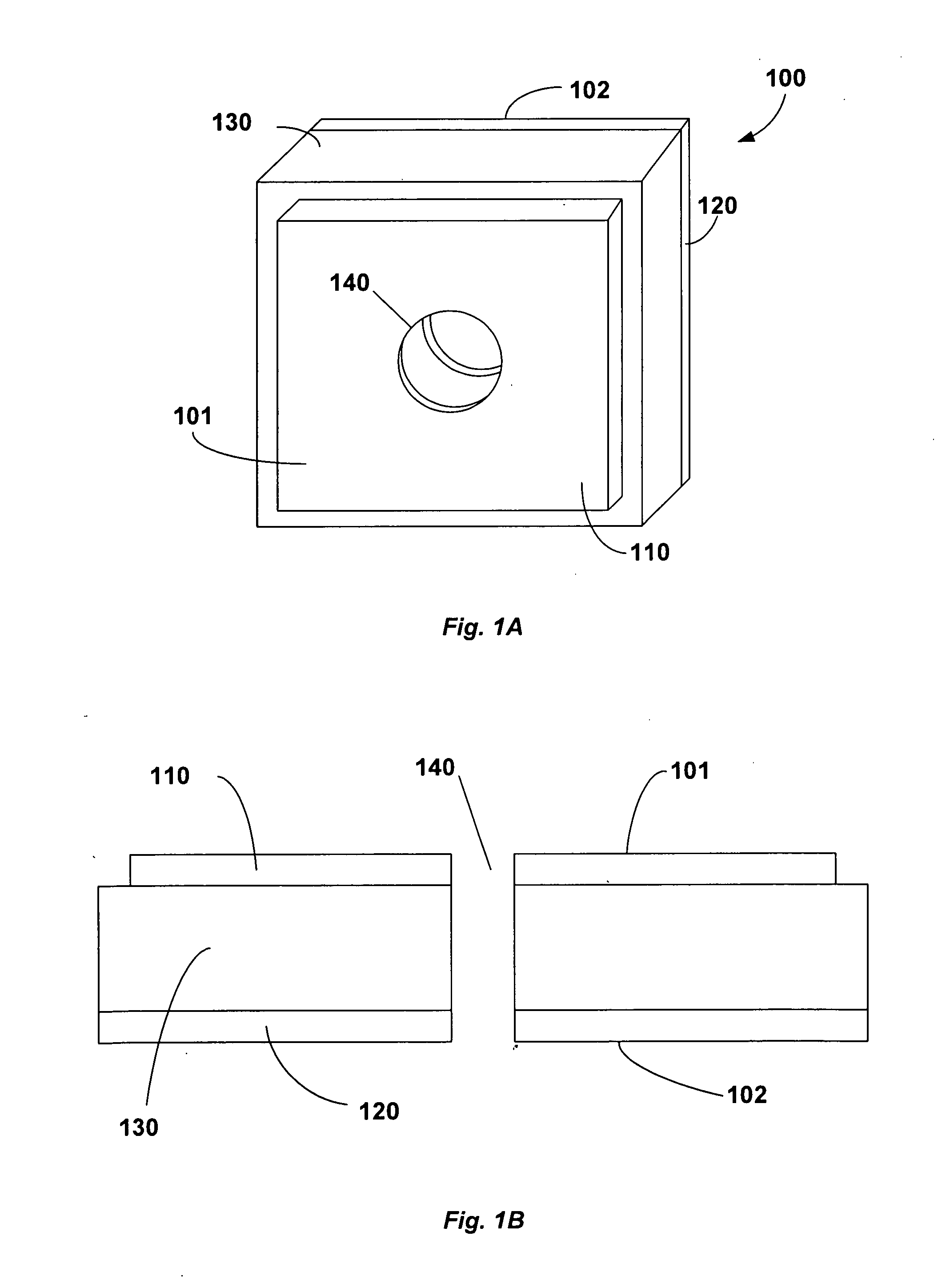
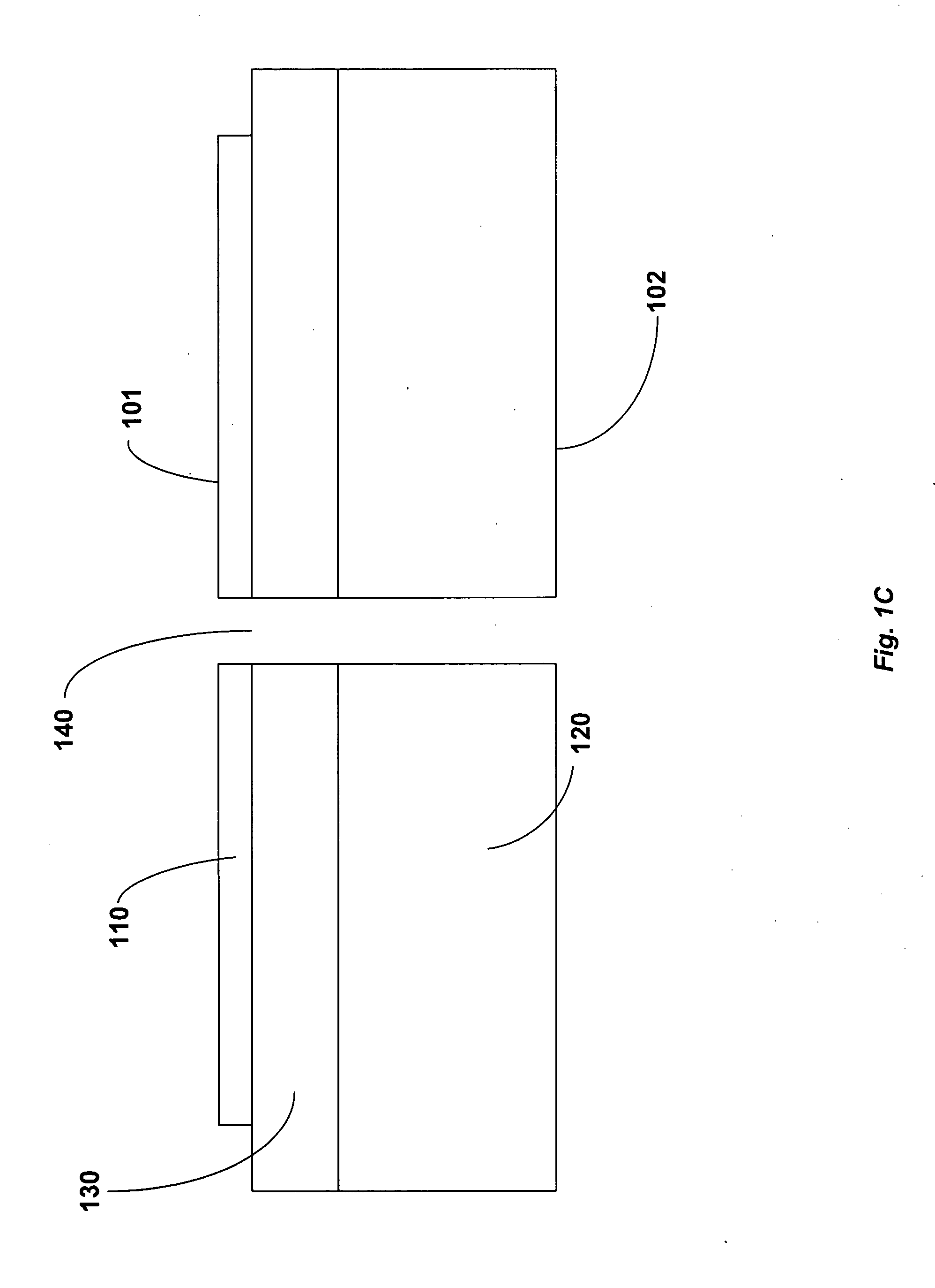
[0035]Referring now in detail to the drawing figures, wherein like reference numerals represent like parts throughout the several views, FIG. 1A illustrates a frontal perspective view of an exemplary embodiment of a microplasma device. In all of the Figures, the microplasma device(s) and features thereof are not illustrated to scale. The Figures are intended to clearly illustrate all of the elements and their functional relationships, rather than actual relative proportions. The microplasma device 100 can comprise a first electrode 110 and a second electrode 120. The first and second electrodes, 110 and 120 can be separated by a dielectric 130. The microplasma device 100 can comprises a first side 101 and a second side 102.

[0036]The microplasma device 100 can further include an aperture 140. The aperture 140 can traverse the width of the microplasma device 100, forming a cylindrical channel through the first electrode 110, dielectric 130, and second electrode 120. The cross-section ...


PUM


Abstract

A method and system for desorbing and ionizing molecules from a sample for mass spectrometry using a microplasma device is disclosed. The system and method relies upon a microplasma device, or array of such devices, to partially ionize a gas to form a microplasma. The ionized gas can be a mixture of a noble gas, such as neon or argon, and hydrogen (H2). The ionized gas can form a effluent stream directed onto the surface of a sample to desorb molecules from the remainder of the sample. The desorbed molecules can be ionized by the effluent stream as they leave the surface of the sample. The ionization process can include: photoionization, penning ionization, chemical ionization (proton transfer), and electron impact ionization. The ionized particles from the sample can be directed to a mass spectrometer for analysis. This can produce spatially-resolved mass spectral data, and can be conducted concurrently with another imaging system, such as a microscope.

Description

CROSS REFERENCE TO RELATED APPLICATIONS[0001]This application claims benefit under 35 U.S.C. § 119(e) of U.S. Provisional Patent Application Ser. No. 60 / 987,162, filed 12 Nov. 2007, and 61 / 107,886, filed 23 Oct. 2008, both of which applications are hereby incorporated by reference.BACKGROUND OF THE INVENTION[0002]1. Field of the Invention[0003]The present invention relates generally to microplasma-assisted desorption and ionization. In particular, the invention relates to a microplasma device serving as an ion source for a mass spectrometer.[0004]2. Description of Related Art[0005]Mass spectrometry is an analytical technique that identifies the chemical composition of a compound or sample based on the mass-to-charge ratio of charged particles. The technique requires a portion of the sample to be chemically fragmented and the fragmented segments to be ionized into charged particles. These particles are then passed into any type of mass spectrometer, which will determine their mass-to...

Claims


Application Information

Patent Timeline
IPC IPC(8): B01D59/44
CPCH01J49/162H01J49/142
Inventor ORLANDO, THOMAS MICHAELSYMONDS, JOSHUA MILBOURNE
Owner GEORGIA TECH RES CORP
Why Eureka
Try Eureka