Power receiving device, and electronic apparatus and non-contact charging system using the same

a technology of power receiving device and electronic equipment, which is applied in the direction of secondary battery servicing/maintenance, electrochemical generators, safety/protection circuits, etc., can solve the problems of reducing reducing the capacity and needs of secondary batteries, and increasing the weight of electronic equipment, so as to reduce the efficiency of power receiving and suppress heating

Active Publication Date: 2009-05-14
KK TOSHIBA +1
View PDF15 Cites 87 Cited by
  • Summary
  • Abstract
  • Description
  • Claims
  • Application Information

AI Technical Summary

Benefits of technology

[0015]An object of the present invention is to provide a power receiving device capable of suppressing an overcurrent generated on the power receiving side by electromagnetic induction, and thereby suppressing heating and decrease in power receiving efficiency due to the overcurrent, an electronic apparatus using the same, and a non-contact charging system.

Problems solved by technology

However, the secondary battery has a limit in capacity and needs to be charged once every few days or every few weeks.
However, electronic apparatuses are becoming lighter in weight along with the downsizing and thickness reduction of electronic apparatuses in recent years, and thereby a problem arises such that the contact pressure between electrodes of the power receiving device and electrodes of the power feeding device becomes insufficient, thereby causing charging failure.
Conventional non-contact charging methods mainly use a nickel-hydrogen battery as the secondary battery, and hence have a problem that many of them take charging time of about eight hours.
However, the ferrite becomes fragile when processed to be thin, and hence is poor in shock resistance.
A problem can easily occur in the power receiving device due to dropping of the device or the like.
Specifically, when the flat coil is used, magnetic flux passing through the flat coil is interlinked with a substrate or the like in the apparatus, and thus an overcurrent generated due to electromagnetic induction causes heating in the apparatus.
Accordingly, large power cannot be transmitted, and a problem that the charging time becomes long arises.
For example, when power transmission rate is raised ignoring the heating, carbon dioxide gas is generated in the Li-ion secondary battery, and there is concern that expansion and explosion or the like occurs.
Therefore, when it is attempted to increase power transmission rate in the non-contact charging method, the problem of heating due to the overcurrent cannot be ignored.
Thus, the power receiving devices to which conventional non-contact charging methods are applied have insufficient measures for the overcurrent generated by electromagnetic induction and heating based on this.
The generation of overcurrent leads to generation of noise, and further becomes a factor to decrease charging efficiency.

Method used


Image

  • Power receiving device, and electronic apparatus and non-contact charging system using the same
  • Power receiving device, and electronic apparatus and non-contact charging system using the same
  • Power receiving device, and electronic apparatus and non-contact charging system using the same

Examples


example 1

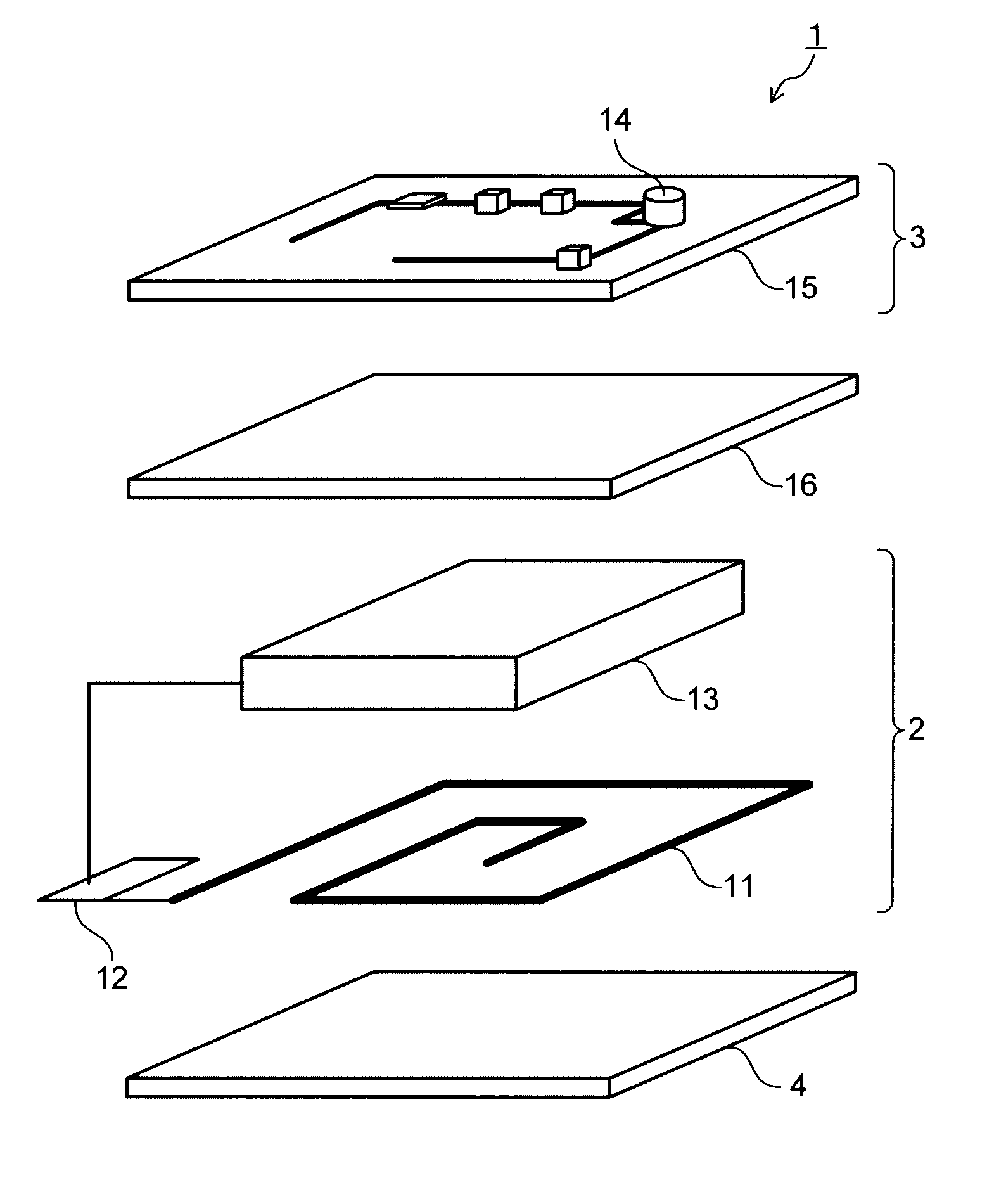
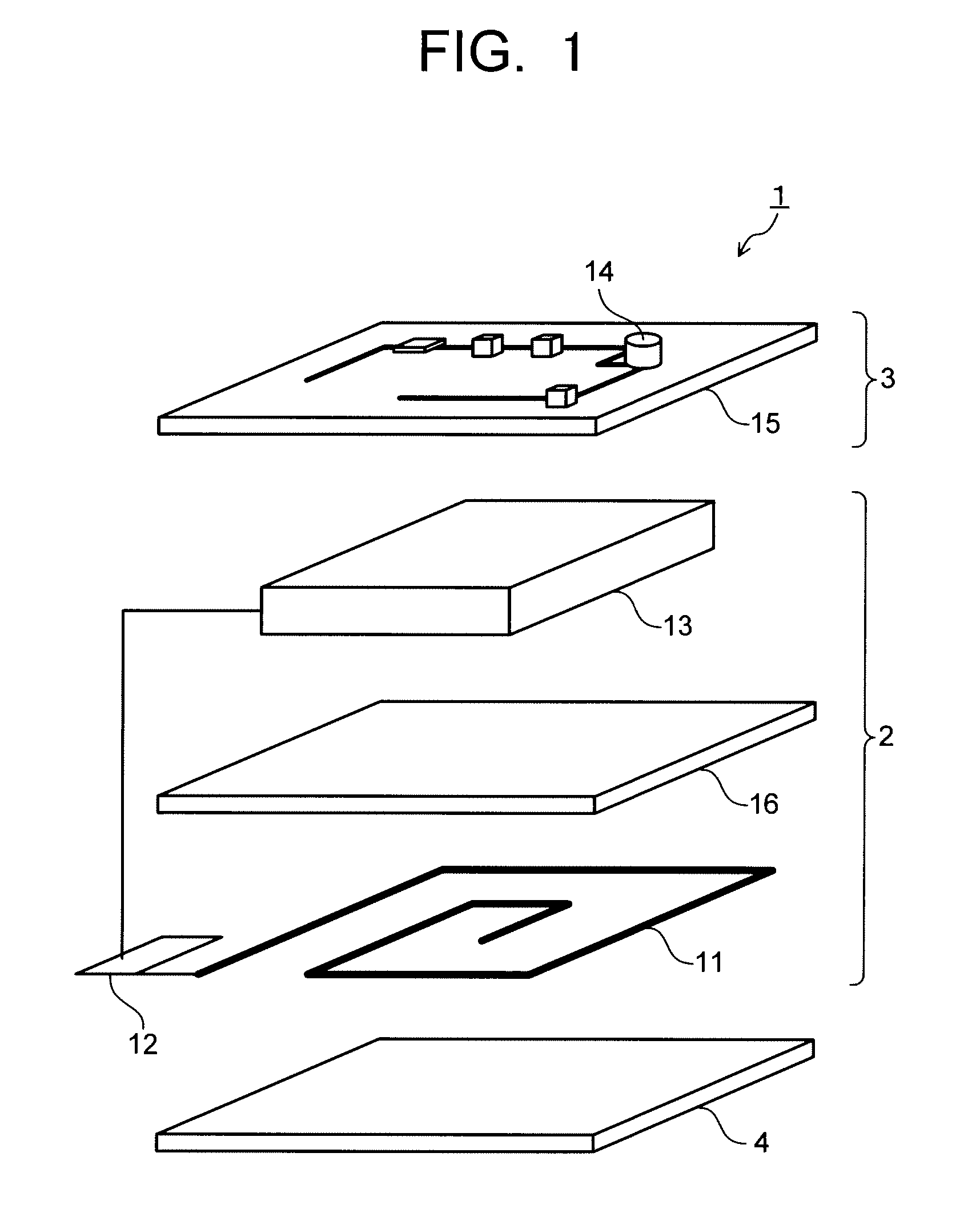
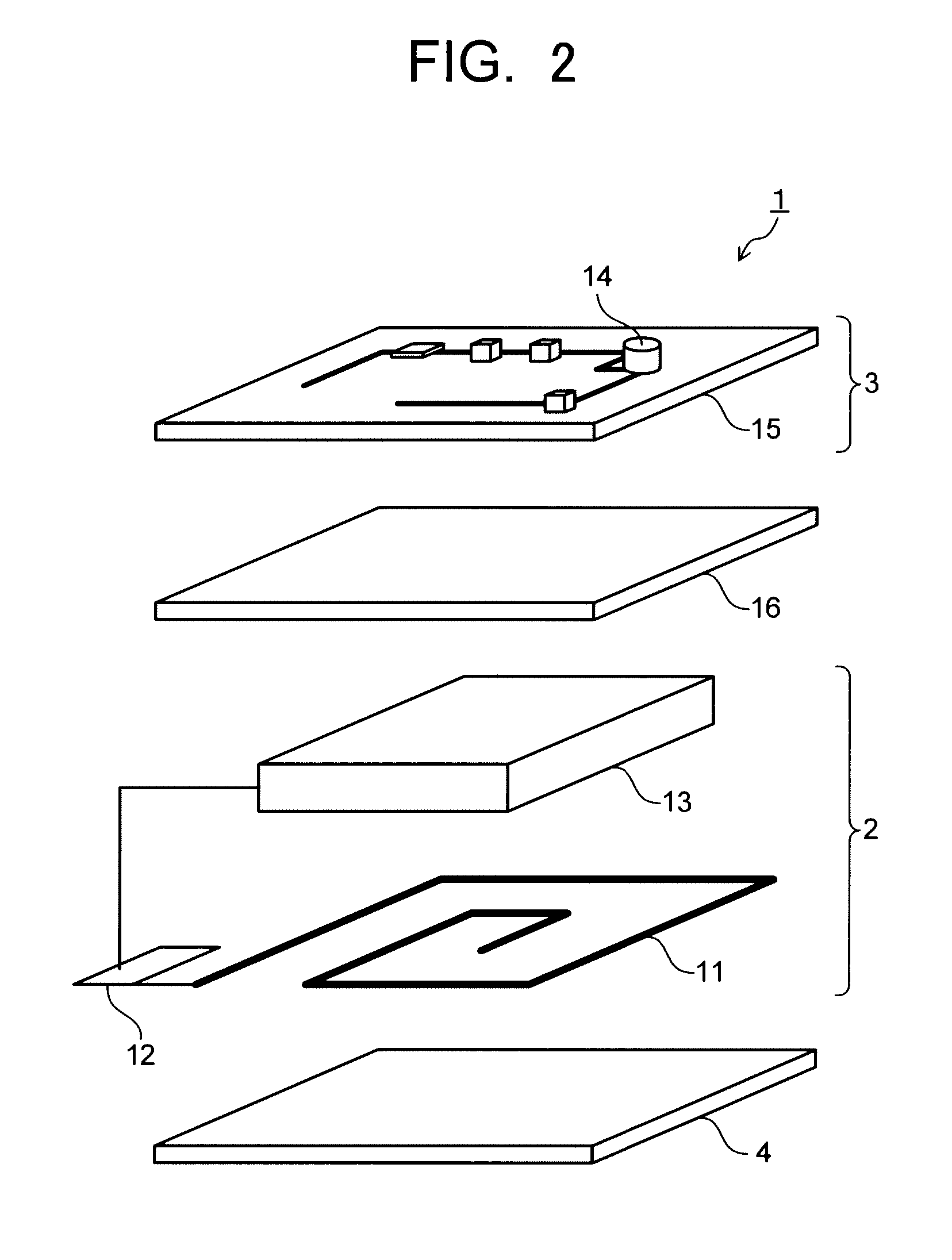
[0084]As a magnetic foil, there was prepared an amorphous alloy thin ribbon with a real component μr′ of relative permeability of 5000, an average plate thickness of 18 μm, and constitution of CO70Fe5Si5B20 (atomic ratio). No thermal treatment is performed on the amorphous alloy thin ribbon. The amorphous alloy thin ribbon has a shape with the protruding amount do of the outer peripheral portion being 6 mm. This amorphous alloy thin ribbon was arranged, as shown in FIG. 1, between the secondary coil (power receiving coil 11) and the secondary battery 13. A mobile phone using a power receiving device having such a magnetic foil and the non-contact charging system were designated as example 1.

examples 2 to 10

[0085]Using an amorphous alloy thin ribbon with the same constitution as the example 1, power receiving devices were made similarly to the example 1 except that the thermal treatment condition, the average plate thickness, and the number of stacks are changed to the conditions shown in Table 1. Mobile phones using these power receiving devices and non-contact charging systems were designated as examples 2 to 10.

examples 11 to 14

[0086]As magnetic foils, amorphous alloy thin ribbons each having constitution of Fe78B14Si8 (atomic ratio) were prepared. The thermal treatment condition, the average plate thickness, and the number of stacks of these amorphous alloy thin ribbons are as shown in Table 1. Power receiving devices were made similarly to the example 1 except using such amorphous alloy thin ribbons. Mobile phones using these power receiving devices and non-contact charging systems were designated as examples 11 to 14.


PUM

PropertyMeasurementUnit
charging timeaaaaaaaaaa
thicknessaaaaaaaaaa
alternating voltageaaaaaaaaaa

Abstract

An electronic apparatus (1) includes a power receiving device (2) and an electronic apparatus main body (3). The power receiving device (2) includes a power receiving coil (11) having a spiral coil, a rectifier (12), and a secondary battery (13). The electronic apparatus main body (3) includes an electronic device (14) and a circuit board (15). A magnetic foil (16) is arranged in at least one position between the spiral coil (11) and the secondary battery (13), the rectifier (12), the electronic device (14), or the circuit board (15). The magnetic foil (16) has a μr′·t value expressed as the product of the real component μr′ of relative permeability and the plate thickness t of 30000 or larger.

Description

TECHNICAL FIELD[0001]The present invention relates to a power receiving device applied for non-contact charging, and an electronic apparatus and a non-contact charging system using the same.BACKGROUND ART[0002]In recent years, development of portable communication apparatuses is proceeding remarkably, and among others, downsizing and thickness reduction of mobile phones are in rapid progress. Other than mobile phones, downsizing and thickness reduction are in progress also for electronic apparatuses such as handy cameras (portable video cameras or the like), cordless telephones, laptop PCs (notebook sized PCs), and the like. Provided with a secondary battery mounted on an electronic apparatus main body, they are structured to be usable without plugging to an outlet, thereby increasing portability and convenience. However, the secondary battery has a limit in capacity and needs to be charged once every few days or every few weeks.[0003]As charging methods, there are contact charging ...

Claims


Application Information

Patent Timeline
Patent Type & Authority Applications(United States)
IPC IPC(8): H02J7/00H01F38/14
CPCH01F3/00H01F38/14H02J7/025H01M10/425H01M10/46H01M10/052H02J50/10H02J7/00302Y02E60/10H01F27/36H01F10/13H02J50/005
Inventor INOUE, TETSUOKUSAKA, TAKAO
Owner KK TOSHIBA
Why Eureka
Try Eureka