
Achromatic Converter Of A Spatial Distribution Of Polarization Of Light

a technology of achromatic converter and spatial distribution, applied in the field of optical elements, can solve the problems of phase shift between these two waves, inability to provide practical solutions to existing state of the art, and achromatic performance, and achieve the effect of reducing the loss of fresnel in visual displays

Inactive Publication Date: 2009-05-14
JDS UNIPHASE CORP
View PDF9 Cites 49 Cited by
  • Summary
  • Abstract
  • Description
  • Claims
  • Application Information

AI Technical Summary

Benefits of technology

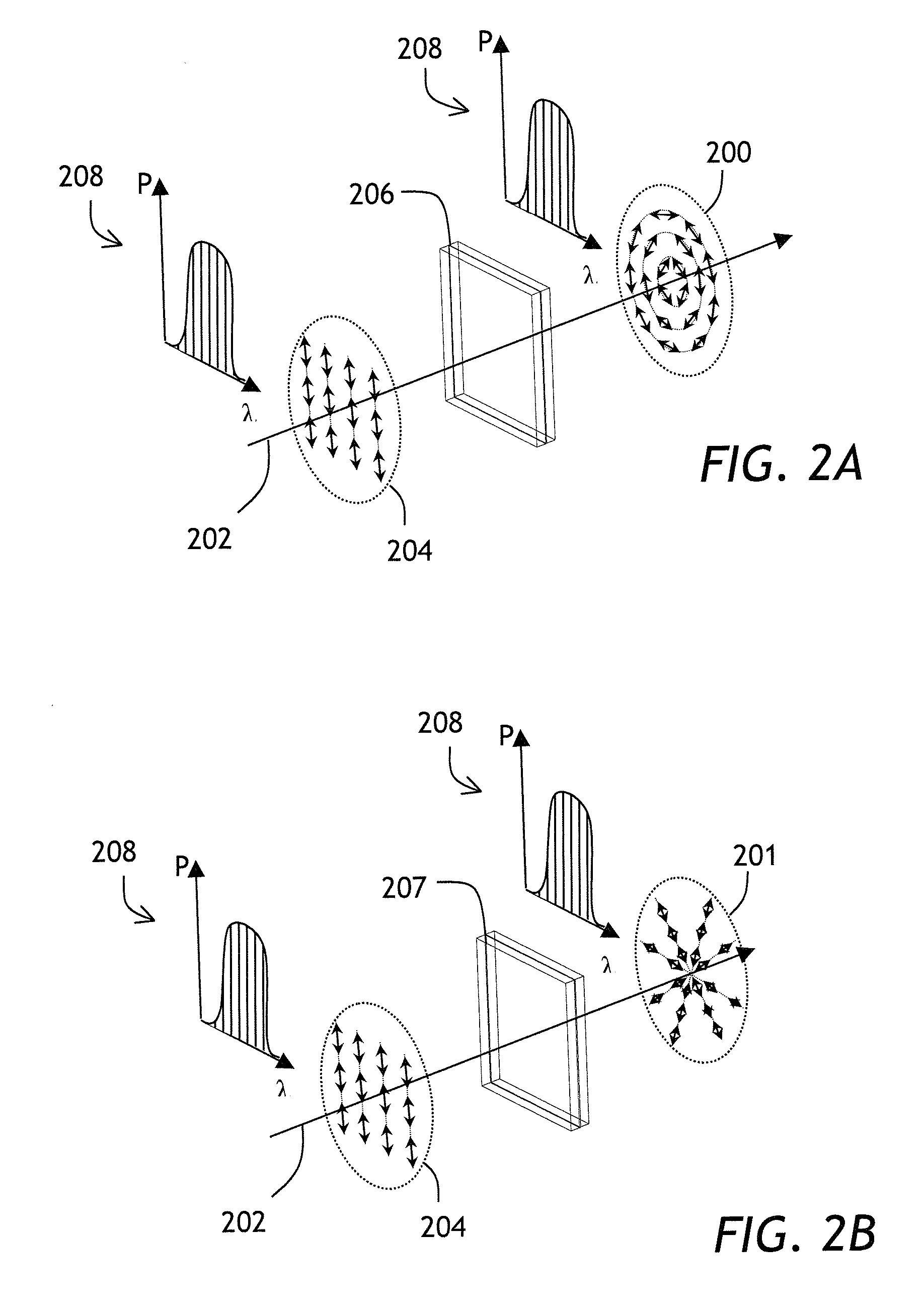
[0013]In accordance with the invention there is provided an optical element for converting a lateral distribution of polarization of an optical beam having at least one wavelength band characterized by a center wavelength and a bandwidth, from a first to a second pre-determined lateral distribution of polarization, wherein the optical element comprises a stack of birefringent layers, wherein the birefringence of each layer of the stack is characterized by a retardance that is substantially constant across the layer, and a direction of a local axis of birefringence that varies, smoothly and gradually, across the layer, and wherein the variations of the direction of the local axes of birefringence of the layers are coordinated therebetween, so as to convert the distribution of polarization of the optical beam from the first to the second distribution of polarization across the entire wavelength band of the optical beam.
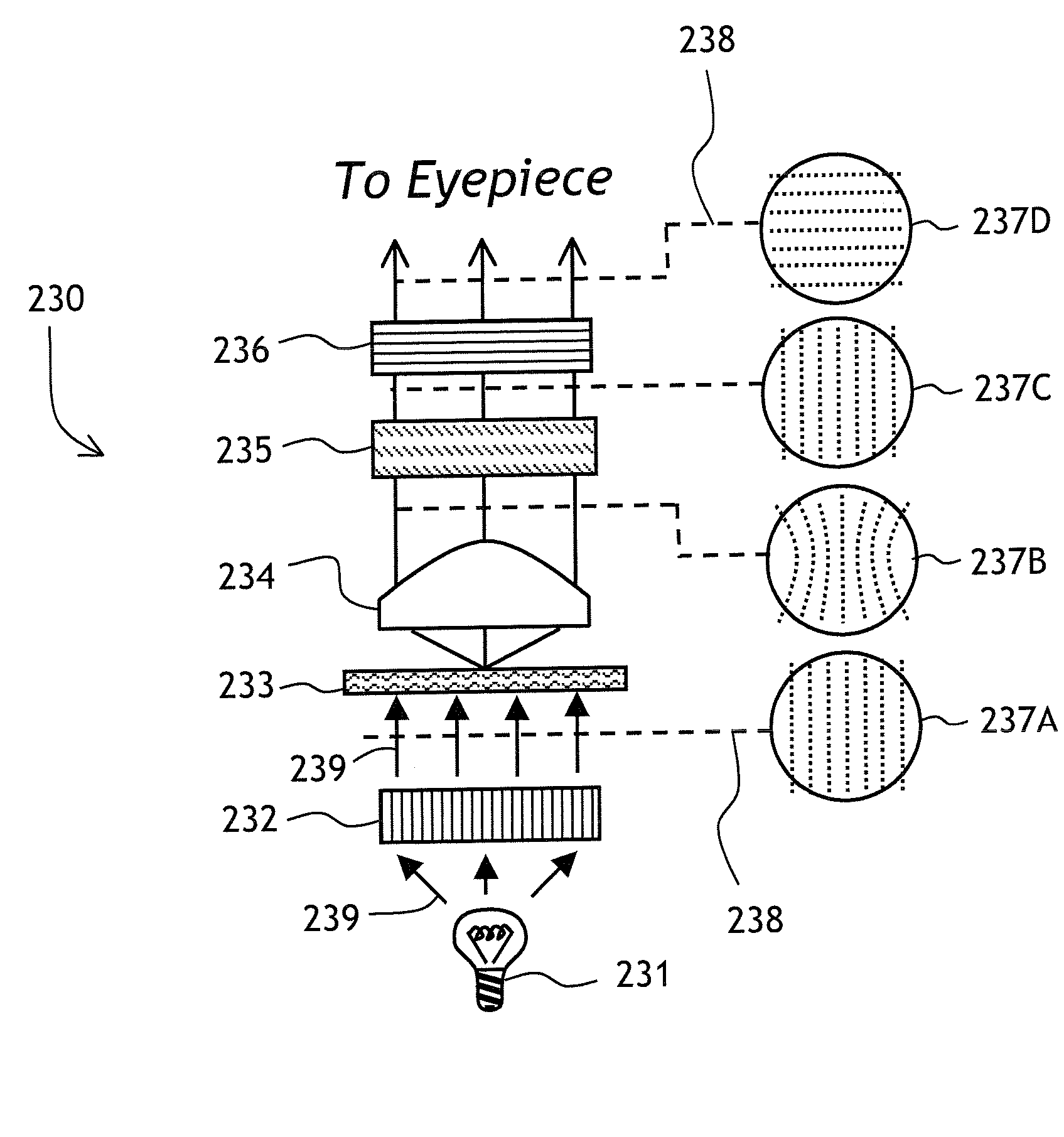
[0016]In accordance with yet another aspect of the invention there is further provided a use of the above described optical elements which includes correcting spatial polarization aberrations and, or creating polarization vortices and, or reducing Fresnel losses in visual displays; polarization microscopy; photolithography; imaging; optical data storage; authenticating documents, goods, or articles; and femtosecond micromachining.

Problems solved by technology

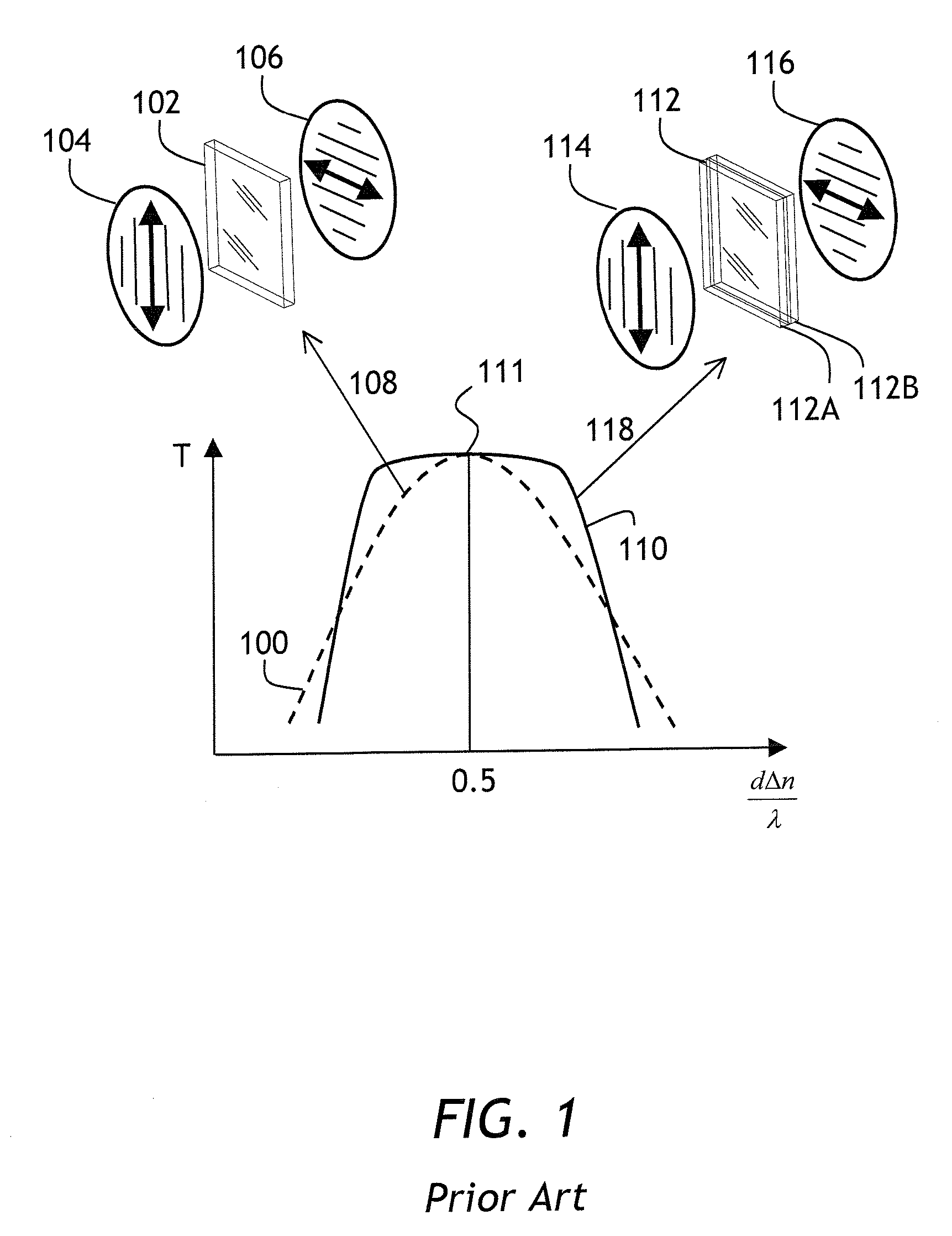
Due to different refractive indices, the two waves travel through the material at different speeds, which results in a phase shift between these two waves.
The prior art methods of generating polarization vortex beams share a common drawback related to the fact that a spatially varying HWP of the prior art has a retardation of one half of a wavelength at one wavelength only.
Therefore, the existing state of the art does not provide practical solutions for many potential applications where an achromatic or polychromatic performance of a polarization distribution-forming optical element is required.
The approaches to achieving achromatic performance of spatially variant optical retarders based on using uniform retardation films or liquid crystal layers suffer from the drawback of a limited range of output polarization states over which the achromaticity is achieved.
The approaches based on subwavelength gratings do not have this disadvantage; however, at least for the visible spectral range, they have to rely on rather exotic and not very well developed technologies, such as nano-imprint lithography.
Still further, in the pixelated retarder structures of the prior art such as a liquid crystal display or a discrete array of subwavelength gratings, an undesirable diffraction of light can occur at sharp boundaries between areas having differing values of retardation.

Method used


Image

  • Achromatic Converter Of A Spatial Distribution Of Polarization Of Light
  • Achromatic Converter Of A Spatial Distribution Of Polarization Of Light
  • Achromatic Converter Of A Spatial Distribution Of Polarization Of Light

Examples


embodiment a

[0068]This particular embodiment of a polarization converter for achromatically rotating an input linear polarization distribution φin(x,y) by the amount Δφ(x,y), with the resulting spectral bandwidth of PCE being substantially the same for any Δφ, and the magnitude of PCE being not smaller than for the specific case Δφ=π / 2 considered earlier, consists of three birefringent layers having retardation Γnom=λnom / 2 and a distribution of the angles of local optical axes θ1, θ2, and θ3 defined as follows:

θ1(Δϕ,ϕin)={ϕin+Δϕ(a-δπ / 2)forΔϕ≤π2ϕin+ΔϕΔϕ[π2(a-δπ / 2)+(Δϕ-π2)(a+δπ / 2)]forπ2<Δϕ≤π(7)θ2(Δϕ,ϕin)=ϕin+bΔϕ(8)θ3(Δϕ,ϕin)={ϕin+Δϕ(c+δπ / 2)forΔϕ≤π2ϕin+ΔϕΔϕ[π2(c+δπ / 2)+(Δϕ-π2)(c-δπ / 2)]forπ2<Δϕ≤π(9)

wherein a=⅞, b=½, c=⅛, and δ is a modifier angle that is adjusted produce the desired range of achromaticity and the level of polarization conversion for Δφ=π / 2. An optimized value of δ of 1.5°˜2.0° allows one to achieve a high degree of polarization conversion over most of the visible spectrum; how...

embodiment b

[0071]The Embodiment B is an improvement of the Embodiment A considered above, particularly for 7π / 8in(x,y) by the amount Δφ(x,y), with the resulting spectral bandwidth of PCE being substantially the same for any Δφ and the magnitude of PCE being not smaller than for the specific case Δφ=π / 2 considered earlier, consists of three birefringent layers having retardation Γnom=λnom / 2 and a distribution of the angles of local optical axes θ1, θ2, and θ3 defined in the same way as in (7), (8), and (9), respectively. However, the parameters a and c are defined differently:

a={78forΔϕ≤7π8Δϕπfor7π8<Δϕ≤π(10)b=1 / 2(11)c={18forΔϕ≤7π81-Δϕπfor7π8<Δϕ≤π(12)

[0072]An optimized value of δ of 1.5°˜2.0° allows one to achieve a high degree of polarization conversion over most of the visible spectrum for Δφ=π / 2; however the values of 0°≦δ≦6° can still be used.

[0073]Turning now to FIG. 15, the angles θ1, θ2, and θ3 are plotted as a function of Δφ. The angles θ1, θ2, and θ3 are calculated by using formul...

embodiment c

[0075]This particular embodiment of a polarization converter for achromatically rotating an input linear polarization distribution φin(x,y) by the amount Δφ(x,y), with the resulting spectral bandwidth of PCE being substantially the same for any Δφ and the magnitude of PCE being not smaller than for the specific case Δφ=π / 2 considered earlier, consists of three birefringent layers having retardation Γnom=λnom / 2 and a distribution of the angles of local optical axes θ1, θ2, and θ3 defined as follows:

θ1(Δϕ,ϕin)={ϕin+Δϕ(a-δπ / 2)forΔϕ≤π2ϕin+ΔϕΔϕ[π2(a-δπ / 2)+(Δϕ-π2)(a+δπ / 2)]forπ2<Δϕ≤7π8ϕin+ΔϕΔϕθ1(7π / 8,0)+(Δϕ-7π / 8)(π-θ1(7π / 8,0))π / 8for7π8<Δϕ≤π(13)θ2(Δϕ,ϕin)=ϕin+bΔϕ(14)θ3(Δϕ,ϕin)={ϕin+Δϕ(c+δπ / 2)forΔϕ≤π2ϕin+ΔϕΔϕ[π2(c+δπ / 2)+(Δϕ-π2)(c-δπ / 2)]forπ2<Δϕ≤7π8ϕin+ΔϕΔϕθ3(7π / 8,0)+(Δϕ-7π / 8)(-θ3(7π / 8,0))π / 8for7π8<Δϕ≤π(15)

wherein a=⅞, b=½, c=⅛, and δ is a modifier angle that is adjusted produce the desired range of achromaticity and the level of polarization conversion over the most of the visibl...


PUM


Abstract

An achromatic converter of spatial distribution of polarization from a first to a second pre-defined distribution of polarization is described. The converter comprises a plurality of photo-aligned quarter-wave or half-wave liquid crystal polymer layers, wherein the patterns of alignment of the layers are correlated with each other so as to make polarization conversion achromatic. Achromatic polarization vortices can be formed. The polarization conversion efficiencies over 97% have been demonstrated over most of the visible spectrum of light. The polarization converters can be used in imaging, photolithography, optical tweezers, micromachining, and other applications.

Description

CROSS-REFERENCE TO RELATED APPLICATIONS[0001]The present invention claims priority from U.S. Provisional Patent Application No. 60 / 987,931, filed Nov. 14, 2007, which is incorporated herein by reference.TECHNICAL FIELD[0002]The present invention is related to optical elements for converting the spatial distribution of polarization of light from a first to a second pre-determined spatial distribution of polarization, and in particular for converting said distribution over a broad range of wavelengths of light.BACKGROUND OF THE INVENTION[0003]A waveplate, or an optical retarder, is an optical device that alters a polarization state of an incident light by introducing a pre-determined phase shift to a phase between two orthogonally polarized components of the incident light. Conventionally, the introduced phase shift is referred to as the waveplate retardance and is measured in fractions of wavelength multiplied by 2π. A waveplate that adds a phase shift of π between the orthogonal pol...

Claims


Application Information

Patent Timeline
Patent Type & Authority Applications(United States)
IPC IPC(8): G02B5/30G02B1/08
CPCG02B5/3025G02F2413/09G02B27/28G02B5/3083G02F1/133631
Inventor SHEMO, DAVID M.ZIEBA, JERRY M.
Owner JDS UNIPHASE CORP
Learn More