Optical Disk Device

a technology of optical discs and optical discs, applied in the direction of digital signal error detection/correction, instruments, recording signal processing, etc., can solve the problems of inability to conduct accurate tilt control, increase the manufacturing cost of optical disc apparatuses, and error may still occur, so as to improve the reliability of recording and reproduction operations, the effect of avoiding the influence of thermal shock

Inactive Publication Date: 2009-05-14
PANASONIC CORP
View PDF6 Cites 6 Cited by
  • Summary
  • Abstract
  • Description
  • Claims
  • Application Information

AI Technical Summary

Benefits of technology

[0052]The optical disc apparatus according to the present invention has an arrangement wherein the aberration correcting means includes a spherical aberration correcting means for correcting a spherical aberration. With this arrangement, the tilt margin for the optical disc apparatus becomes large, and also, it is possible to correct a spherical aberration that is caused by the coma aberration correction. Consequently, it is possible to improve the reliability of the recording and reproduction operations by the optical disc apparatus.
[0053]The optical disc apparatus according to the present invention has an arrangement wherein during an activation of the optical disc apparatus, in a case where the tilt of the optical disc detected by the tilt detecting means exceeds a predetermined angle, the activation of the optical disc apparatus is started all over again. With this arrangement, it is possible to activate the optical disc apparatus while the influence of a thermal shock tilt is avoided. Consequently, it is possible to improve the reliability of the recording and reproduction operations by the optical disc apparatus.
[0054]The optical disc apparatus according to the present invention has an arrangement wherein the activation of the optical disc apparatus is started all over again based on the tilt of the optical disc detected by the tilt detecting means at an outer circumference position on the optical disc. With this arrangement, it is possible to activate the optical disc apparatus while the influence of a thermal shock tilt is avoided. Consequently, it is possible to improve the reliability of the recording and reproduction operations by the optical disc apparatus.
[0055]The optical disc apparatus according to the present invention has an arrangement to further include: a correction amount determining means for determining the amount of the correction performed by the coma aberration correcting means based on the tilt of the optical disc detected by the tilt detecting means, wherein during the activation of the optical disc apparatus, in a case where the amount of the correction determined by the correction amount determining means exceeds a predetermined value, the activation of the optical disc apparatus is started all over again. With this arrangement, it is possible to activate the optical disc apparatus while the influence of a thermal shock tilt is avoided. Consequently, it is possible to improve the reliability of recording and reproduction operations by the optical disc apparatus.
[0056]The optical disc apparatus according to the present invention has an arrangement wherein during an activation of the optical disc apparatus that has been started all over again, in a case where the tilt of the optical disc detected by the tilt detecting means exceeds a predetermined angle once again, a recording operation of the optical disc apparatus is prohibited. With this arrangement, it is possible to prevent excessive light emission from the light source. Consequently, it is possible to improve the performance of the optical disc apparatus.
[0057]The optical disc apparatus according to the present invention has an arrangement wherein during the activation of the optical disc apparatus that has been started all over again, in a case where the amount of the correction determined by the correction amount determining means exceeds a predetermined value once again, the recording operation of the optical disc apparatus is prohibited. With this arrangement, it is possible to prevent excessive light emission from the light source. Consequently, it is possible to improve the performance of the optical disc apparatus.

Problems solved by technology

Thus, the problem arises where it is not possible to conduct accurate tilt control.
As a result, the problem arises where the manufacturing costs of the optical disc apparatuses increase.
Further, even if the zero point offset is adjusted in the assembly step of the apparatuses, an error may still occur due to changes in the tilt sensor 900 over the course of time and the temperature characteristics.
Such an error that occurs after the assembly step raises another problem whereby the tilt sensor 900 is not able to conduct accurate tilt control.

Method used


Image

  • Optical Disk Device
  • Optical Disk Device
  • Optical Disk Device

Examples


first embodiment

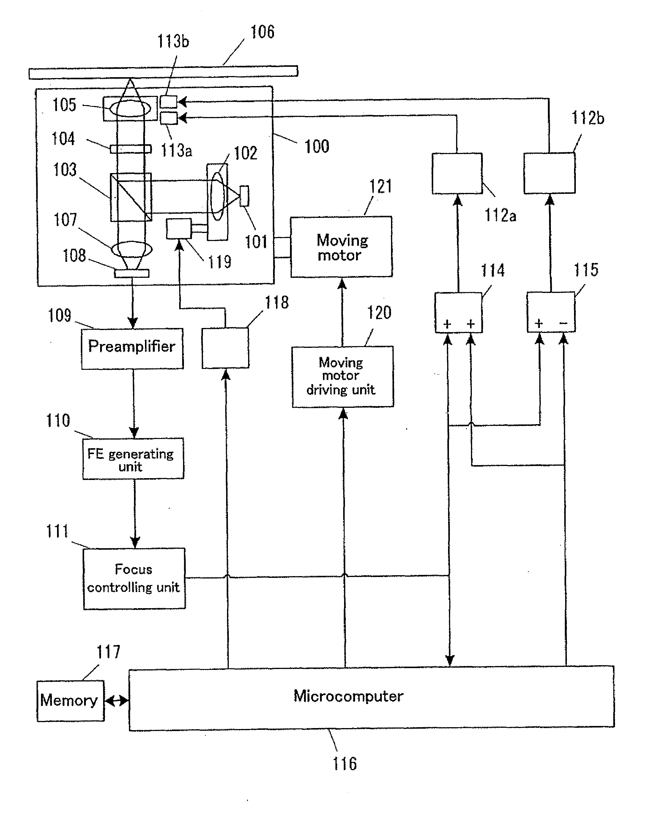
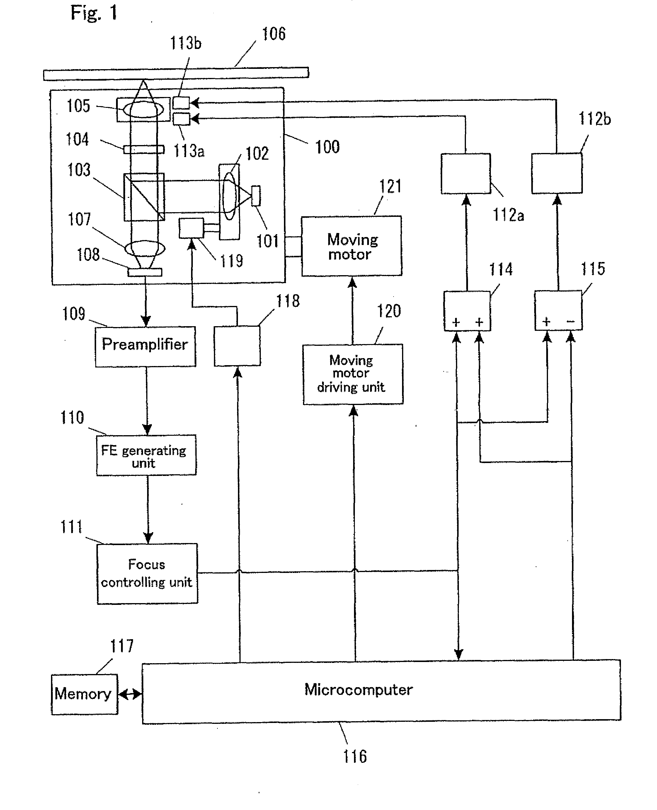
[0070]FIG. 1 is a block diagram showing a structure of an optical disc apparatus according to First Embodiment of the present invention. It should be noted that the constituent elements that are also included in the conventional optical disc apparatus are referred to by the same reference numbers, and thus the description thereof will be omitted.

[0071]In FIG. 1, an adder 114 is an electric circuit for performing an addition on a focus driving signal and an output from a microcomputer 116. A subtracter 115 is an electric circuit for performing a subtraction on a focus driving signal and an output from the microcomputer 116. A first focus driving unit 112a is a circuit for outputting a focus actuator driving signal based on an output signal from the adder 114. A second focus driving unit 112b is a circuit for outputting a focus actuator driving signal based on an output signal from the subtracter 115. A first focus actuator 113a and a second focus actuator 113b are mounted having the ...

second embodiment

[0124]FIG. 10 is a block diagram showing a structure of an optical disc apparatus according to Second Embodiment of the present invention. It should be noted that the constituent elements that are also included in the optical disc apparatuses according to First Embodiment and the conventional technique are referred to by using the same reference numbers, and therefore the description thereof will be omitted.

[0125]An optical disc 206 is an optical disc (a multi-layer optical disc) that has a plurality of data layers (i.e. two or more data layers). Herein, the optical disc 206 is a dual layer optical disc having two data layers. The optical disc apparatus shown in FIG. 10 is capable of performing recording and reproduction operations on a dual layer optical disc.

[0126]Like in First Embodiment, the optical disc apparatus according to the present embodiment performs the coma aberration correction using the objective lens 105. Thus, it is possible to improve the reliability of the perfor...


PUM

PropertyMeasurementUnit
circumferenceaaaaaaaaaa
tilt angleaaaaaaaaaa
densityaaaaaaaaaa

Abstract

The optical disc apparatus according to the present invention includes a tilt detecting means; a coma aberration correcting means; and a spherical aberration correcting means. Based on the result of a tilt detection, the amount of the correction performed by the coma aberration correcting means is determined so that the amount of correction is constant for the whole circumference of an optical disc, and then a spherical aberration is corrected by the spherical aberration correcting means. Thus, it is possible to correct the spherical aberration that has occurred due to the coma aberration correcting means, while the tilt margin is secured, thereby improving the reliability of reproduction and recording by the optical disc apparatus. Further, the optical disc apparatus according to the present invention is configured, in the case where a thermal shock tilt has occurred during the activation of the apparatus, to wait until the thermal shock tilt has settled. Thus, it is possible to perform the activation while the influence of the thermal shock tilt is avoided, thereby improving the reliability of the recording and reproduction operations by the optical disc apparatus.

Description

TECHNICAL FIELD[0001]The present invention relates to to an optical disc apparatus for reproducing signals on an optical disc (which may be any one of various types of optical discs including reproduction-only discs and recording / reproduction discs) using a light source such as a laser, and particularly relates to an optical disc apparatus including a coma aberration correcting means for correcting a coma aberration of a light beam in the radial direction on an optical disc.BACKGROUND ART[0002]In an optical disc apparatus, an angle by which the data surface of an optical disc is out of alignment with a direction perpendicular to the optical axis of a light beam irradiated onto the optical disc is called a tilt angle. When the tilt angle is not zero, we say that a tilt has occurred. As optical discs have been developed to have high density, degradation of jitters in a recording signal or a reproduction signal becomes significant due to tilts occurring with optical discs and optical d...

Claims


Application Information

Patent Timeline
Patent Type & Authority Applications(United States)
IPC IPC(8): G11B7/00
CPCG11B7/0945G11B2007/0013G11B7/13925G11B7/0956
Inventor KONDO, KENJIYAMADA, SHINICHIHINO, YASUMORI
Owner PANASONIC CORP
Why Eureka
Try Eureka