Relieving Urban Traffic Congestion

a technology for urban traffic and congestion relief, applied in signalling/lighting devices, external condition input parameters, process and machine control, etc., can solve the problems of increasing traffic congestion, increasing traffic, and affecting more travel, so as to reduce congestion, increase the number of lanes, and increase fuel consumption

Inactive Publication Date: 2009-05-14
DESAI SHITALKUMAR V +1
View PDF32 Cites 74 Cited by
  • Summary
  • Abstract
  • Description
  • Claims
  • Application Information

AI Technical Summary

Benefits of technology

[0034]Woodbury (U.S. Pat. No. 6,328,121) discloses an ultra-narrow enclosed vehicle with a width of about 3 ft, stabilized with the aid of a ballast weight of 950 lbs, giving a curb weight of 1600 lbs. This ballast is the equivalent of about five extra passengers, and results in the need for a correspondingly larger engine or motor and higher fuel consumption.
[0035]Conventional means for reducing congestion include increasing the number of lanes, creating “high occupancy vehicle” (HOV) lanes, adding parallel rail transit, ride sharing, and public or private bus...

Problems solved by technology

Congestion extends to more times of the day and more roads, affects more travel, and creates more extra travel time than in the past.
Congestion levels have risen in all urban size categories, indicating that even smaller areas are not able to keep pace with rising demand.
However, major transportation projects require a significant planning and development time—10 years is not an unrealistic timeframe to go from an idea to a completed project or to an accepted program.
This is a difficult question to answer.
Thus, isolating the effects of roadway construction is difficult, because these other programs and projects make a contribution at the same time.
In any case, the relevancy of the analysis is questionable.
It also concludes that it would be almost impossible to attempt to maintain a constant congestion level with road construction only.
An even larger problem would be to find suitable roads that can be widened, or areas where roads can be added, year after year.
It may be very difficult to convince this many people to begin ridesharing or using public transit.
There has been some success with this solution, and in conjunction with other techniques, there may be some opportunity to slow the mobility decline.
Solutions implemented and suggested to date are generally location specific, require heavy capital investment, involve lengthy temporary traffic diversion affecting traffic at all hours, cause additional temporary congestion during commuting hours, and are expensive.
Developed countries like the United States, could actually afford many of these suggested conventional solutions, although they would still suffer ongoing and worsened congestion until these high-capital-investment projects are completed.
They would still be incurring financial loss of tens of billions of dollars per year until implementation is complete (assuming constant congestion, economic health, and stable fuel prices; we have already observed that congestion has gotten steadily worse every year since 1982).
In addition, the roadway improvement solutions mentioned above are not dynamic in the sense that new capacity would be available for both non-commute hours and commute hours.
These proposals generally require very expensive infras...

Method used


Image

  • Relieving Urban Traffic Congestion
  • Relieving Urban Traffic Congestion
  • Relieving Urban Traffic Congestion

Examples


Embodiment Construction

Preliminary Tests

[0058]In order to understand the traffic congestion problem, three types of simple tests were conducted for both freeways and local arterial streets. The first test was a 92.5-mile round trip on weekdays and weekends, during different months and weather condition over a span of three years. The roads used were TX-190 (East-West) and I-35 (North-South). The travel times for over 300 round trips were measured. In the morning, the trip started between 6:25 am and 6:30 am, and the return trip in the afternoon started between 4:15 pm and 4:30 pm. The morning trip consistently required 43 to 47 min during weekdays. The return trip consistently required at least 63 min. There were occasional incidental delays caused by accidents, disabled vehicles, Oklahoma University game traffic, or severe weather. On weekends, the trips consistently required 43 to 47 min each way.

[0059]The second test was a 32-mile round trip on local arterial streets with three lanes on each side. The ...


PUM


Abstract

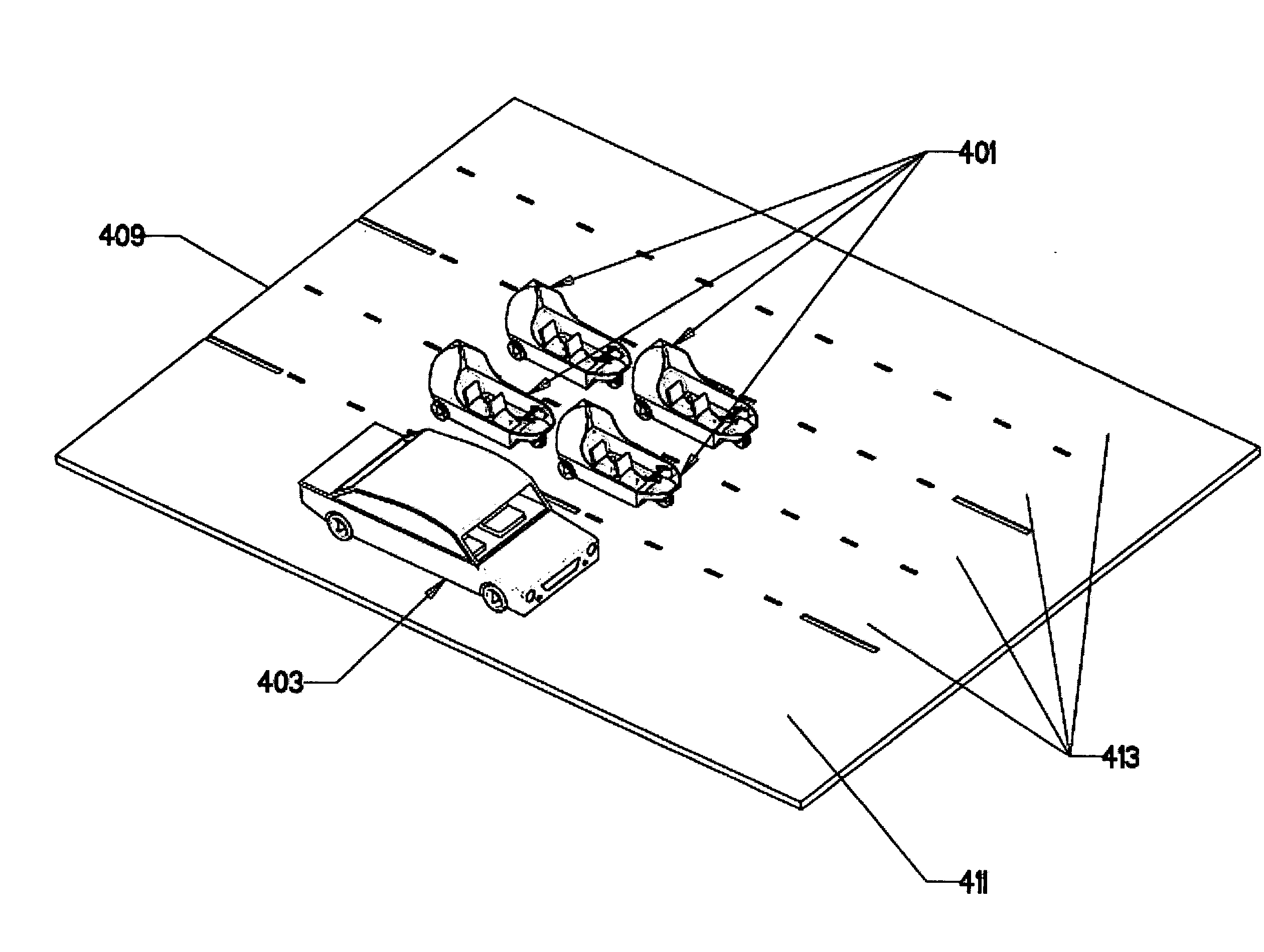
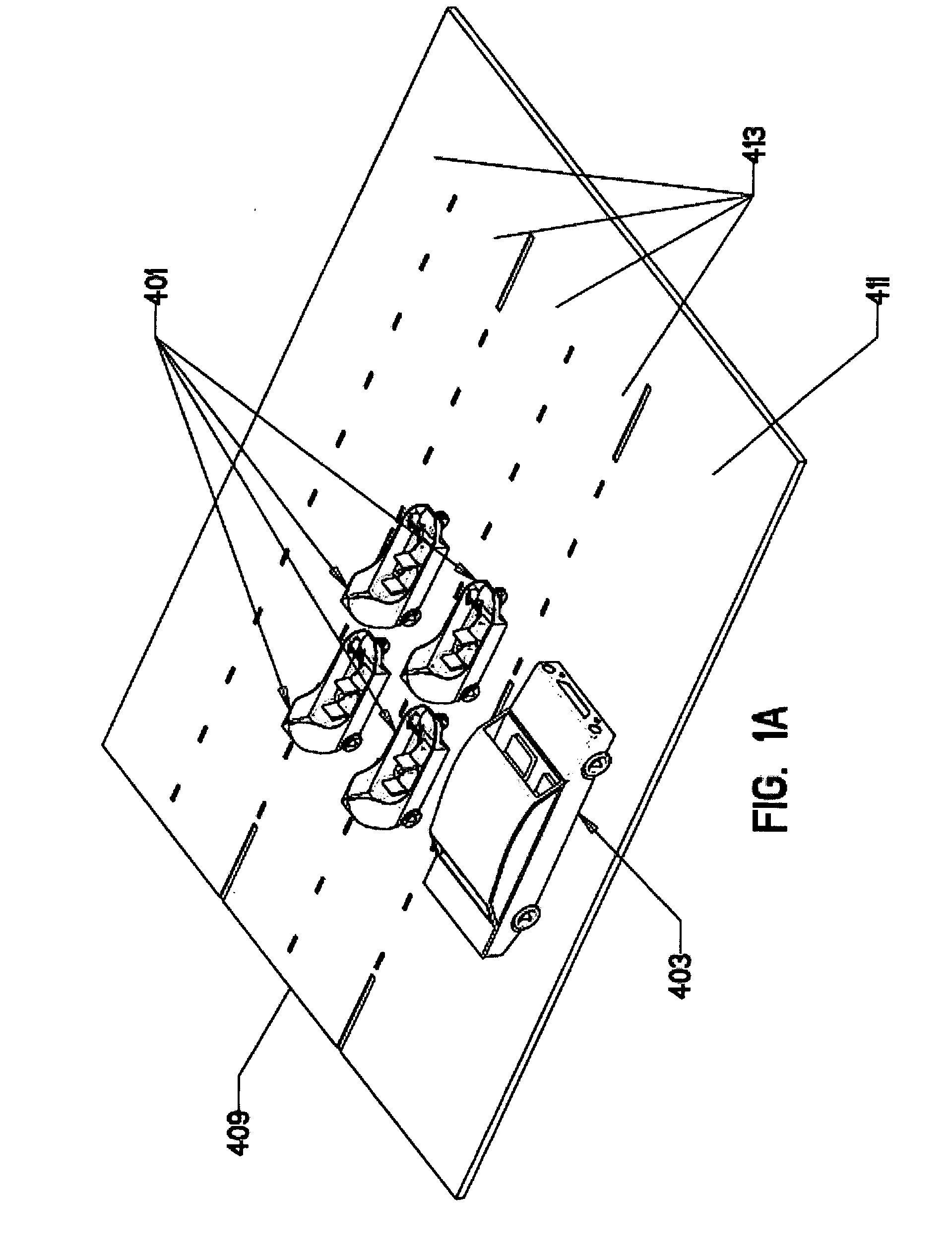
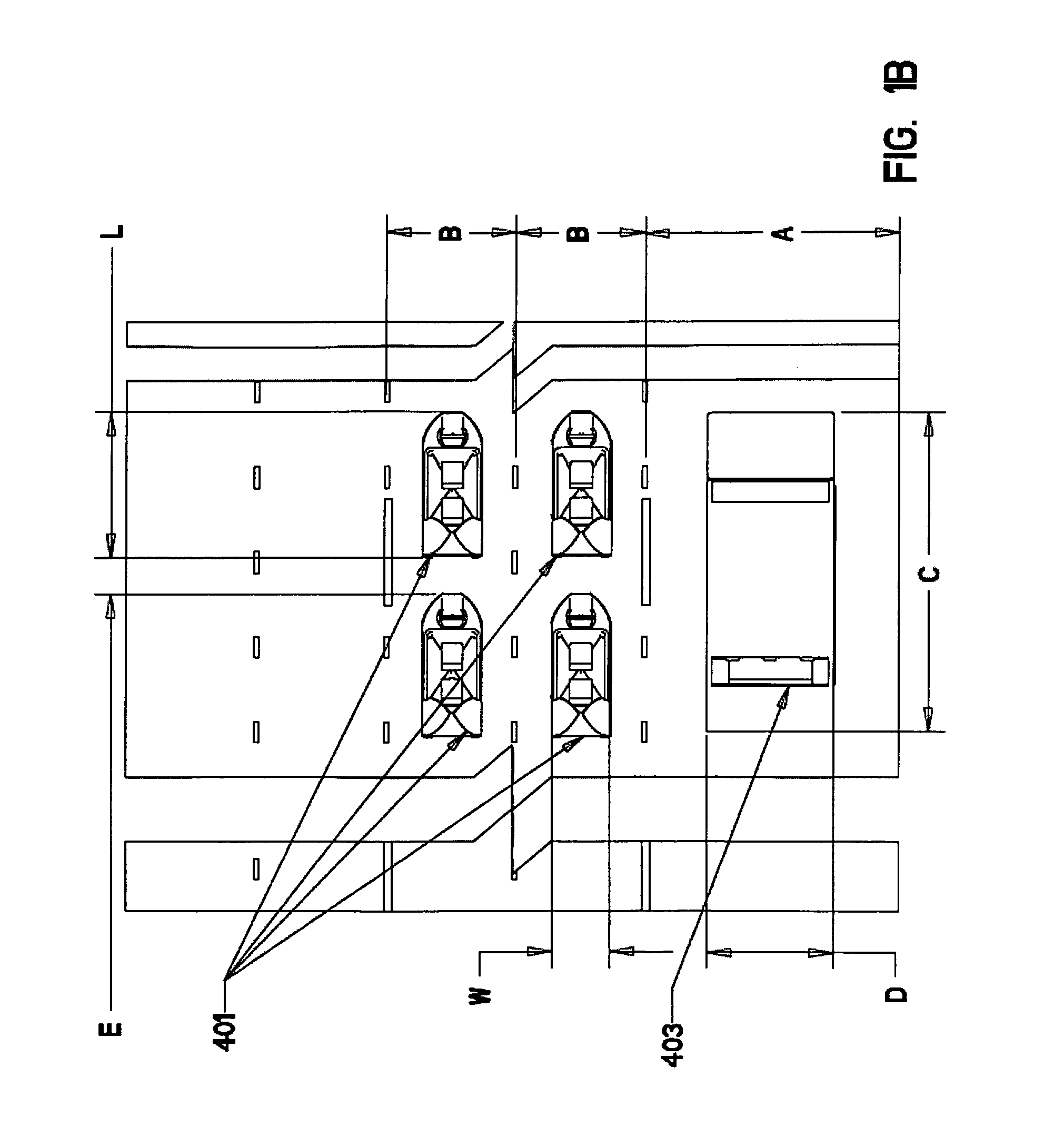
A method of reducing congestion on a roadway is disclosed comprising dividing selected lengths of selected normal lanes of a roadway into two commuter lanes, providing distinctive lane markings to identify the commuter lanes, and dynamically designating selected lengths of selected lanes as either normal lanes or pairs of commuter lanes. In order to dynamically change lane configurations, a set of indicators can be provided as lane markers together with a control system to alter particular lane configurations between normal lanes and commuting lanes both cyclically according to a preprogrammed schedule and dynamically in response to sensed vehicle traffic volume, unusual events such as accidents, weather, and so on. Commuter lanes are designated cyclically and dynamically in response to traffic conditions to increase the capacity of the affected road. Normal lanes are designated at other times. To facilitate entry and exit from designated commuter lanes, transition zones can be provided where entering and exiting commuter lane traffic has right of way.
A commuter vehicle is disclosed for use on commuter lanes. A typical commuter vehicle weighs less than 650 lbs., has at least three wheels, an enclosed seating compartment, and a low center of gravity with at least one occupant. In one embodiment, occupants sit in a near-kneeling position to lower their center of gravity. In, an alternate embodiment also providing a low center of gravity, occupants sit in a recumbent position. A mechanism can be provided to raise and lower the seats to facilitate occupant entry and exit. Occupants can be position in-line, one behind the other. Embodiments with two, three, or more seats can be provided.

Description

CROSS REFERENCE TO RELATED APPLICATIONS[0001]This application claims priority to U.S. Provisional Application No. 60 / 987,449, filed on Nov. 13, 2007, incorporated by reference herein in its entirety.FIELD OF THE INVENTION[0002]The present invention generally relates to methods and vehicles for reducing urban traffic congestion.BACKGROUND OF THE INVENTION[0003]A record 9.16 million barrels per day of motor gasoline was consumed in 2005. The average price of a gallon of gasoline in the United States is approaching four dollars as of June 2008.[0004]Traffic data presented in the 2005 annual Urban Mobility Report by the Texas Transportation Institute at Texas A&M University for peak commuting hours in 85 metropolitan areas in 2005, when the average price of gasoline was $1.45 per gal, showed an annual total of 3.7 billion hours of delay, 2.3 billion gallons of extra fuel used and a total cost of $63.1 billion per year. About 70% of this cost is from fuel costs, so at $4 per gal, this to...

Claims


Application Information

Patent Timeline
IPC IPC(8): E01C23/16B62D61/06B60W30/00E01F9/588
CPCB60N2/01B60W30/12B60W40/04E01C1/002B62D31/003B62D61/08B60W2550/20B60W2554/00
Inventor DESAI, SHITALKUMAR V.DESAI, VIPINCHANDRA M.
Owner DESAI SHITALKUMAR V
Why Eureka
Try Eureka