Laser piercing method and processing apparatus

a laser processing and piercing technology, applied in the direction of laser beam welding apparatus, manufacturing tools, welding/soldering/cutting articles, etc., can solve the problems of deteriorating processing efficiency, deteriorating material yield, and deteriorating processing efficiency, so as to suppress excessive oxidation, high efficiency, and high precision

Active Publication Date: 2009-05-21
NISSAN TANAKA
View PDF9 Cites 13 Cited by
  • Summary
  • Abstract
  • Description
  • Claims
  • Application Information

AI Technical Summary

Benefits of technology

[0130]As a result of using the laser piercing method and the processing apparatus according to the present invention, it is possible to provide a piercing hole having a desired diameter with high efficiency and high precision while suppressing excessive oxidation and to thus decrease the production cost.

Problems solved by technology

Meanwhile, when processing the piercing hole using a pulsed oscillation laser beam, it is possible to improve the precision of the piercing hole diameter, but the processing efficiency may deteriorate greatly.
That is, in the piercing processing, the excessive oxidation and burning of the workpiece W increases the piercing hole diameter, deteriorating the yield of material.
Meanwhile, the piercing processing employing a pulsed oscillation laser beam can improve the precision of the piercing hole diameter but greatly deteriorates the processing efficiency.

Method used


Image

  • Laser piercing method and processing apparatus
  • Laser piercing method and processing apparatus
  • Laser piercing method and processing apparatus

Examples


first embodiment

[0166]Hereinafter, the present invention will be described with reference to the accompanying drawings.

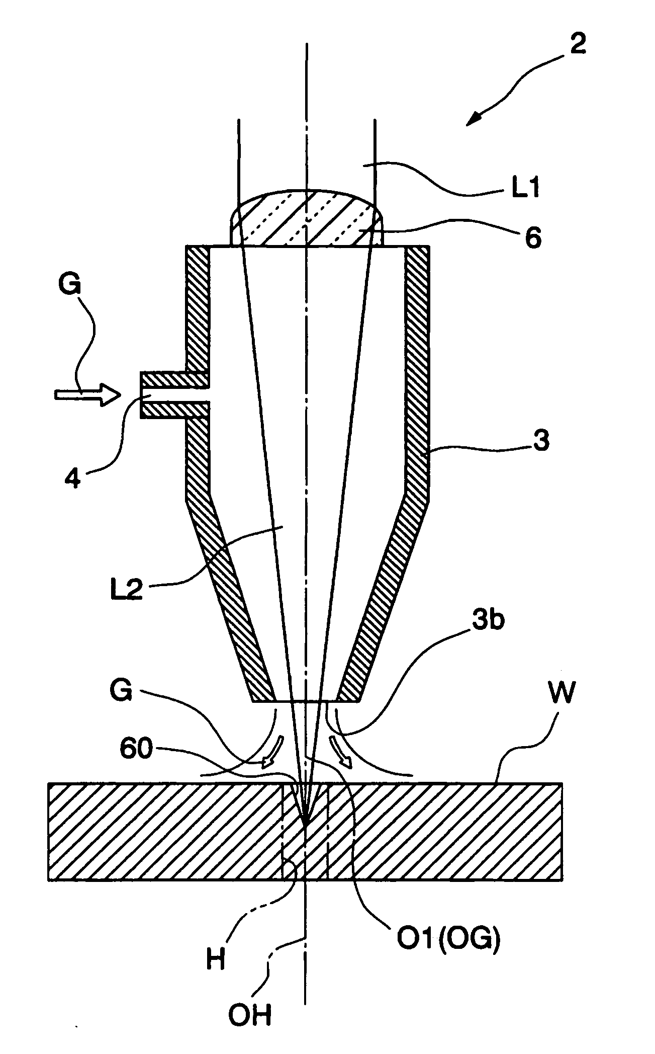
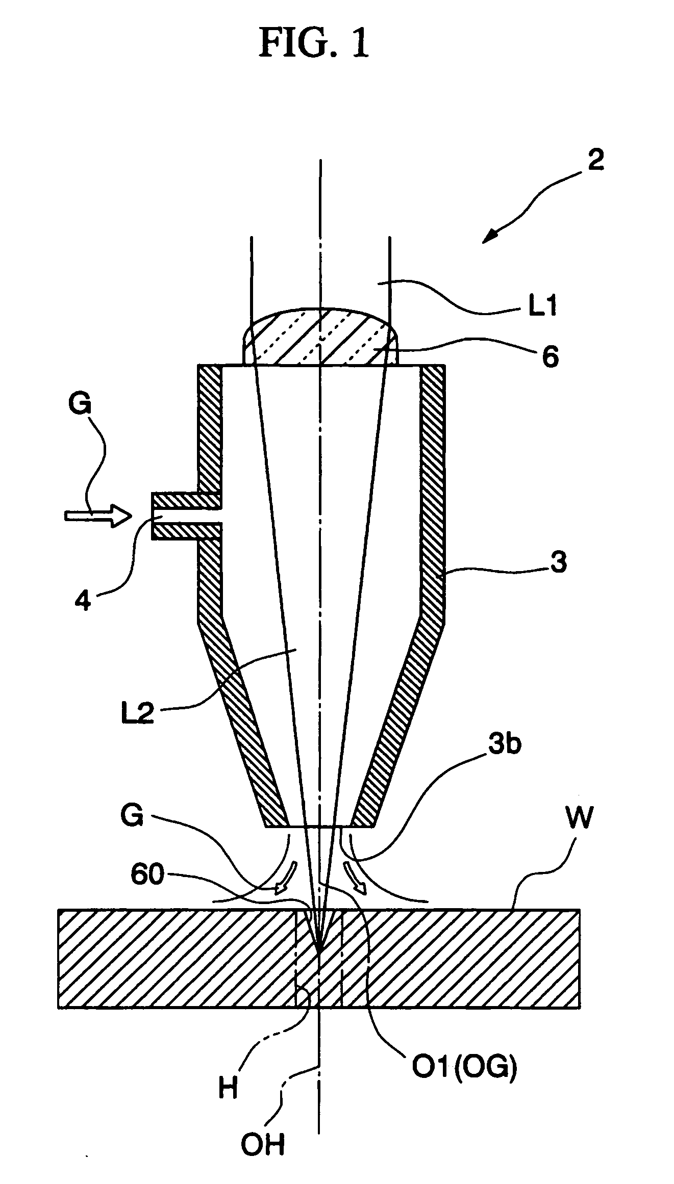
[0167]FIG. 1 shows a laser torch 2 according to a first embodiment, showing the state in which a piercing hole H is processed. The laser torch 2 includes a nozzle 3 and a condenser lens 6. The nozzle has a cylindrical shape, and is configured to condense a laser beam L1 having passed through the condenser lens 6 and to output a laser beam L2 from an injection port 3b.

[0168]The axial line O1 of the nozzle 3 is coaxial to the optical axis of the laser beam L2 and is also coaxial to the central axis of the pressure distribution of an assist gas G injected from the nozzle 3.

[0169]The assist gas G is introduced from an inlet port 4 into the nozzle 3 and is injected from the injection port 3b to react with a workpiece W which was melted and evaporated by the laser beam L2, oxidizing and burning the workpiece W.

[0170]In the present embodiment, a processing start point at the time of proc...

second embodiment

[0336]Hereinafter, the present invention will be described with reference to the accompanying drawings.

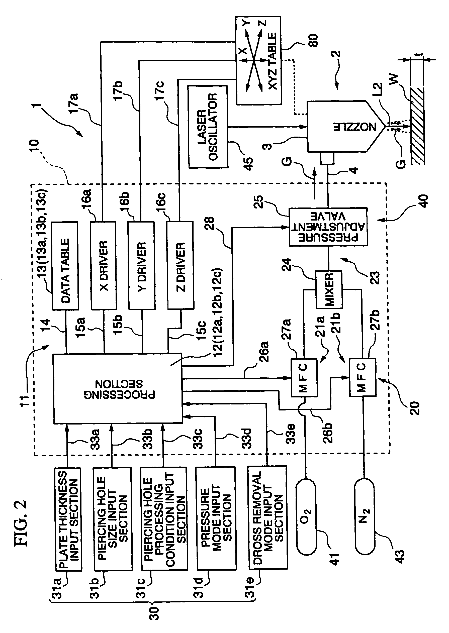
[0337]FIG. 11 is a schematic diagram of a processing apparatus according to the present invention. In FIG. 11, reference numeral 200 denotes a processing apparatus, reference numeral 210 denotes an adjustment section (adjustment means), and reference numeral 211 denotes an oxygen content adjustment section (oxygen content adjustment means).

[0338]The processing apparatus 200 includes an adjustment section 210, a processing data input section 230, an oxygen supply source 241, a nitrogen supply source 243, a laser oscillator 245, and a nozzle 247. The adjustment section 210 is configured to mix oxygen from the oxygen supply source 241 with nitrogen from the nitrogen supply source 243 while adjusting their amounts on the basis of the processing data inputted from the processing data input section 230, to produce an assist gas G having an oxygen content suitable for providing a desired ...


PUM

PropertyMeasurementUnit
thicknessaaaaaaaaaa
pressureaaaaaaaaaa
diameteraaaaaaaaaa

Abstract

A processing apparatus is provided in which a laser beam L2 is irradiated onto a processing portion of a workpiece W, and at the same time as the laser irradiation, an assist gas G is injected toward the processing portion from a nozzle 3 arranged concentric to the laser beam L2 so that the processing portion is covered with the assist gas G, thereby processing a piercing hole H on the processing portion. The apparatus includes control means 10 for processing a piercing hole H while moving the nozzle 3 within the range of 5 mm from a processing start point after the irradiation of the laser beam L2 is started.

Description

TECHNICAL FIELD[0001]The present invention relates to a method for piercing a workpiece with a laser processing apparatus, and more particularly, to a processing apparatus employing the piercing method.[0002]This application is based upon and claims the benefit of priority from the prior Japanese Patent Application Nos. 2005-166996 filed on Jun. 7, 2005, and 2006-106982 filed on Apr. 7, 2006, the entire contents of which are incorporated herein by reference.BACKGROUND ART[0003]In the past, when cutting a workpiece such as a steel plate with a laser processing apparatus, the workpiece is laser-pierced to form a small through-hole with a diameter of several millimeters at a point on the workpiece serving as a cutting start point, and the cutting starts from the through-hole.[0004]The through-hole is important in improving finishing precision of the workpiece without decreasing the yield of material, and is preferably formed to a desired size, as small as possible, but not too small to...

Claims


Application Information

Patent Timeline
Patent Type & Authority Applications(United States)
IPC IPC(8): B23K26/38
CPCB23K26/1405B23K26/381B23K26/385B23K26/402B23K26/401B23K26/4015B23K26/4005B23K26/40B23K26/142B23K26/382B23K26/389B23K2103/04B23K2103/10B23K2103/12B23K2103/14B23K2103/50B23K26/14
Inventor NUMATA, SHINJISANO, YOSHIMI
Owner NISSAN TANAKA
Why Eureka
Try Eureka