Electric power steering device

a technology of electric power steering and steering wheel, which is applied in the direction of non-deflectable wheel steering, underwater vessels, special data processing applications, etc., can solve the problems of steering speed drop, interference with smooth motor rotation, and so on, and achieve the effect of stably applying assist power

Active Publication Date: 2009-05-21
JTEKT CORP
View PDF12 Cites 20 Cited by
  • Summary
  • Abstract
  • Description
  • Claims
  • Application Information

AI Technical Summary

Benefits of technology

[0009]This invention provides an electric power steering device that stably applies an assist power by facilitating rotation of a motor when two phases thereof are driven due to an electrification failure. The invention also provides a method for controlling the electric power steering device.
[0011]According to the above configuration, except for the predetermined angle corresponding to the asymptotic line (a current restriction range in the vicinity of the predetermined rotational angle, when the value of the phase current applied to each phase has a limit), a motor current corresponding to a requested torque can be generated. As a result, even when the electrification failure occurs, the motor can be driven continuously while maintaining the high output performance, without generating a significant torque ripple.
[0013]However, execution of the acceleration control of the above configuration can increase the rotational angular velocity of the motor to prevent the occurrence of the stuck steering wheel. As a result, even during low-speed steering, smooth motor rotation can be achieved and a stable assist power can be provided.
[0014]This invention can provide an electric power steering device that stably applies an assist power by facilitating rotation of a motor when two phases thereof are driven due to an electrification failure. The invention can also provide a method for controlling the electric power steering device.

Problems solved by technology

As a result, due to the fact that the torque in the steering direction (the sum of the steering torque and the assist torque) falls below a reaction torque in a return direction (axial force) in the vicinity of the predetermined rotational angle, a section where the steering speed decreases appears; which might interfere with smooth motor rotation.
Such a phenomenon might cause a so-called stuck steering wheel.

Method used


Image

  • Electric power steering device
  • Electric power steering device
  • Electric power steering device

Examples


first embodiment

[0037]An electric power steering device (EPS) according to the invention is described hereinafter with reference to the drawings.

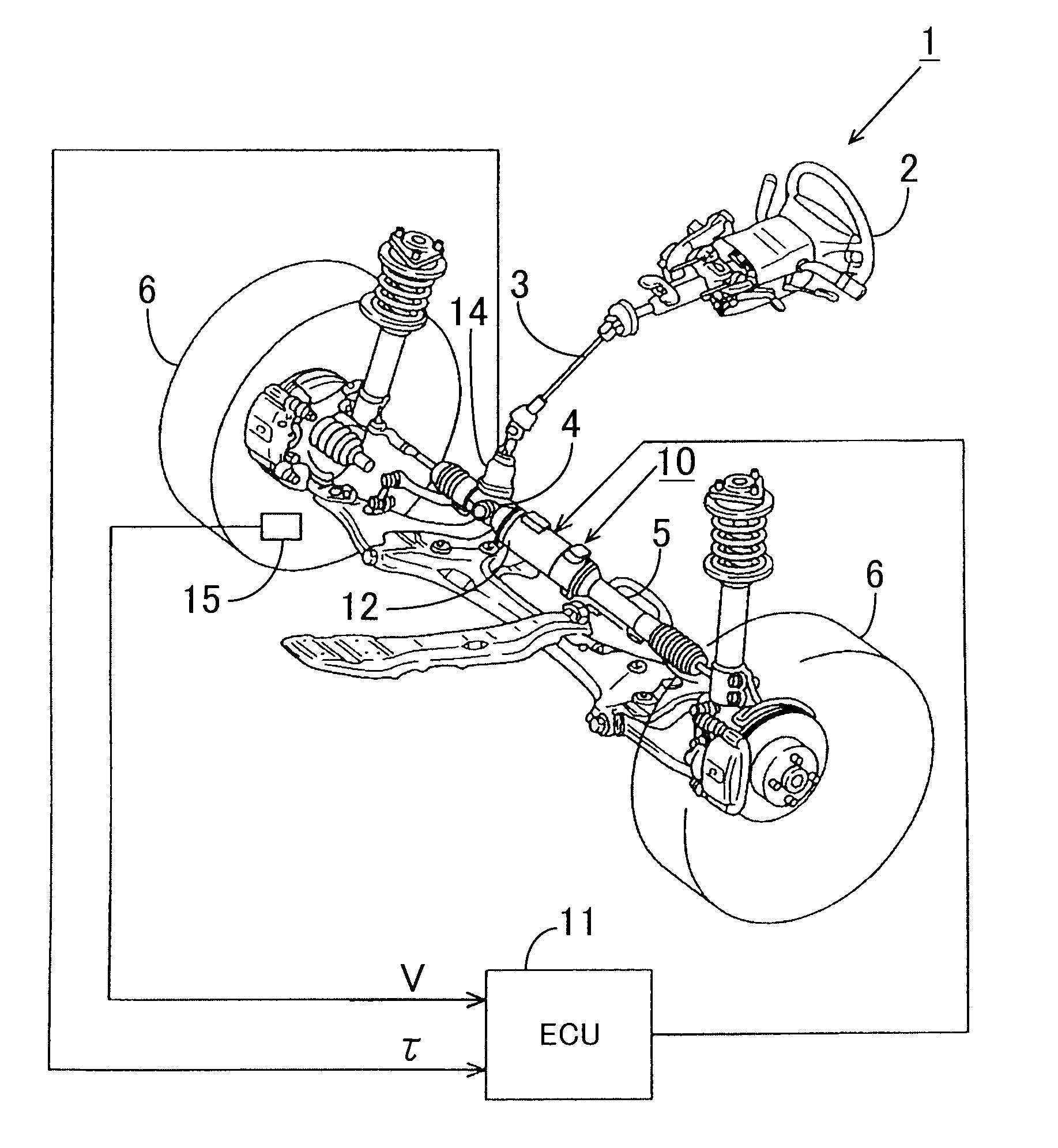
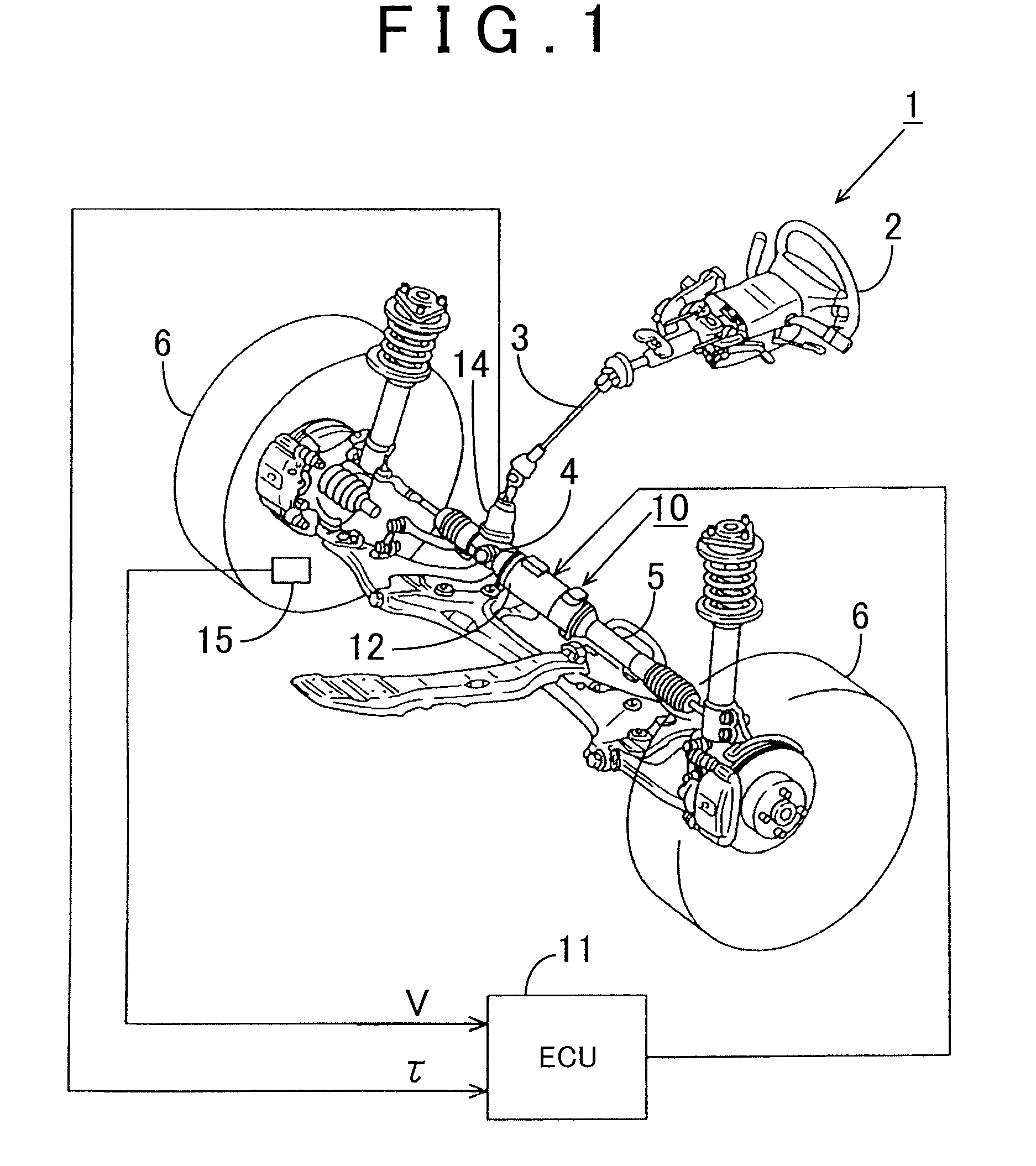
[0038]FIG. 1 is a schematic configuration diagram of an EPS 1 according to the first embodiment of the invention. As shown in the diagram, a steering shaft 3 connected to a steering wheel (steering) 2 is connected to a rack 5 via a rack-and-pinion mechanism 4. When steering is performed, the rotation of the steering shaft 3 is converted into a linear motion of the rack 5 by the rack-and-pinion mechanism 4. Then, the rudder angle of turning wheels 6 is changed by the linear motion of the rack 5.

[0039]The EPS 1 has an EPS actuator 10 which functions as a steering force assisting device for applying an assist power to a steering system to assist its steering operation, and an electrical control unit (ECU) 11 for controlling actuation of the EPS actuator 10.

[0040]The EPS actuator 10 is a so-called rack-type EPS actuator, in which a motor 12 serving as a drive ...

second embodiment

[0124]Next, a second embodiment in which the invention is embodied into the EPS is described with reference to the drawings.

[0125]The only main difference between this embodiment and the first embodiment is the aspect of the acceleration control that is performed for preventing the occurrence of the stuck steering wheel during low-speed steering, the stuck steering wheel being caused by the current restriction. Therefore, for convenience of explanation, the same reference numerals are used for the parts same as those of the first embodiment, and the explanation of these parts are omitted.

[0126]In this embodiment, as the acceleration control that is performed for preventing the occurrence of the stuck steering wheel during low-speed steering, the stuck steering wheel being caused by the current restriction, only the inverse assist control is performed when the steering direction does not match the rotational direction of the motor 12 (see FIG. 14). This invention is characterized in ...


PUM


Abstract

When an electrification failure occurs in any of the phase of a motor, a control device of an electric power steering device executes current control for generating, in each of two electrification phases other than a phase with the electrification failure, a phase current that changes in the form of a secant curve or a cosecant curve based on an asymptotic line, which is a predetermined rotational angle corresponding to the phase with the electrification failure, to thereby continuously output a motor control signal. The control device of the electric power steering device executes current restriction for restricting the phase current within a predetermined range. The control device of the electric power steering device further executes control for accelerating rotation of the motor during two phase drive, in order to prevent the occurrence of a stuck steering wheel during low-speed steering, which is caused as a result of the execution of the current restriction.

Description

INCORPORATION BY REFERENCE[0001]The disclosure of Japanese Patent Application No. 2007-300667 filed on Nov. 20, 2007 including the specification, drawings and abstract is incorporated herein by reference in its entirety.BACKGROUND OF THE INVENTION[0002]1. Field of the Invention[0003]This invention relates to an electric power steering device.[0004]2. Description of the Related Art[0005]Many of the motor control devices that are used in electric power steering devices (EPS) and the like are provided with abnormality detecting means for detecting an abnormality when an electrification failure occurs in any of a three-phase motor (any of U, V and W phases) due to disconnection of a power supply line or a contact failure of a drive circuit. Upon detection of the abnormality, these motor control devices stop the motor control promptly to attain fail safe.[0006]However, the steering characteristics of the EPS change significantly due to the discontinuation of the motor control. In other w...

Claims


Application Information

Patent Timeline
Patent Type & Authority Applications(United States)
IPC IPC(8): B62D5/04B62D6/00B62D119/00
CPCB62D5/0487B62D5/0484
Inventor TAMAIZUMI, TERUTAKA
Owner JTEKT CORP
Why Eureka
Try Eureka