Determination of permeability from damping

a technology of permeability and determination method, applied in the direction of fluid tightness measurement, instruments, structural/machine measurement, etc., can solve the problems of inability to evaluate large samples, limited laboratory testing, and current non-seismic methods of permeability determination

Inactive Publication Date: 2009-05-28
BOISE STATE UNIVERSITY
View PDF18 Cites 14 Cited by
  • Summary
  • Abstract
  • Description
  • Claims
  • Application Information

AI Technical Summary

Benefits of technology

[0015]In use, for example, one may use a porosity log (conventional neutron or sonic) and recordings of SH-waves to obtain damping ratio, followed by locating of the damping ratio on an embodi...

Problems solved by technology

Current non-seismic methods of permeability determination are limited to either laboratory tests (constant head or falling head), or to well tests like draw-down flow testing or drill stem testing in oil wells.
The laboratory tests are restricted to small sample volumes and are not able to evaluate large samples with large grain sizes (ie: cobbles).
Draw-down and...

Method used


Image

  • Determination of permeability from damping
  • Determination of permeability from damping
  • Determination of permeability from damping

Examples


example a

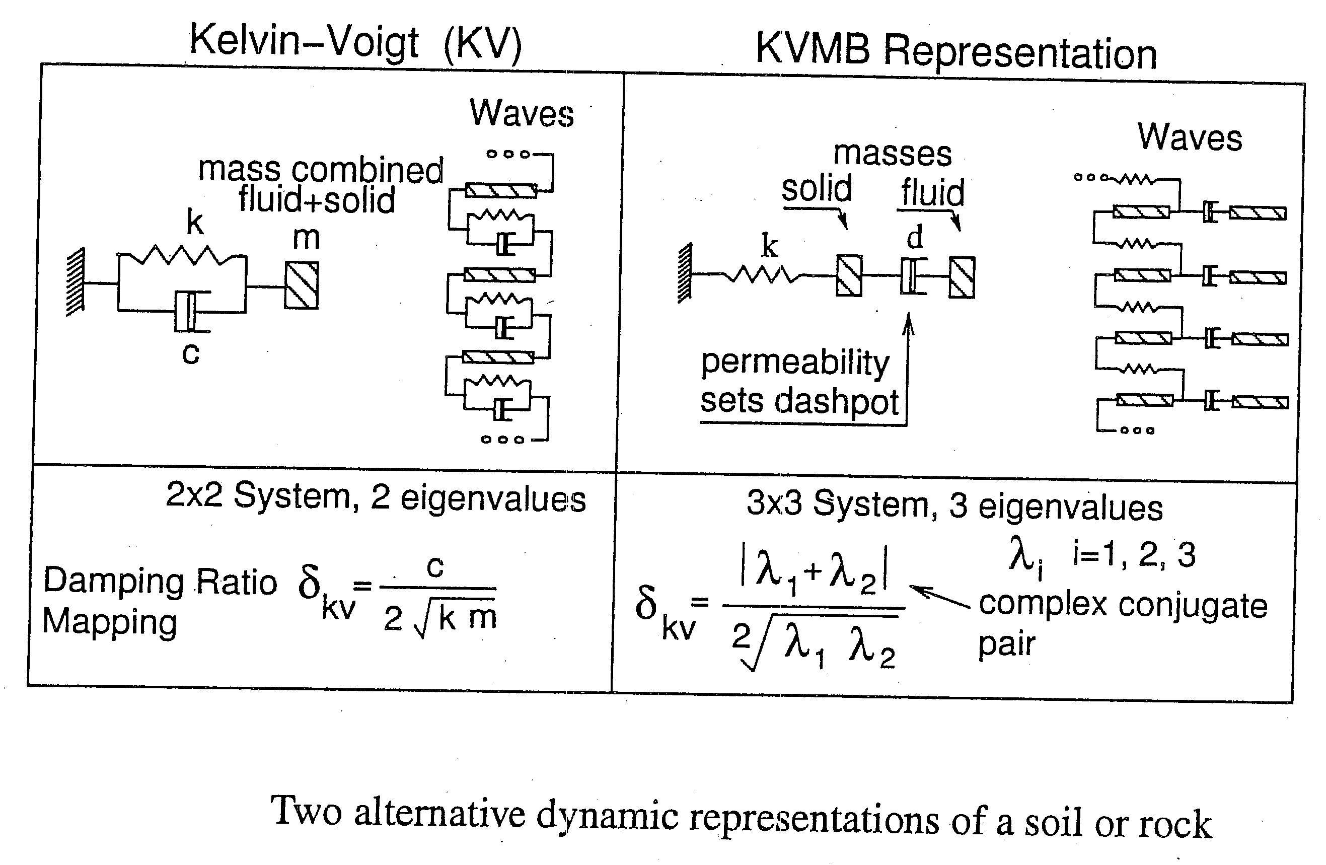
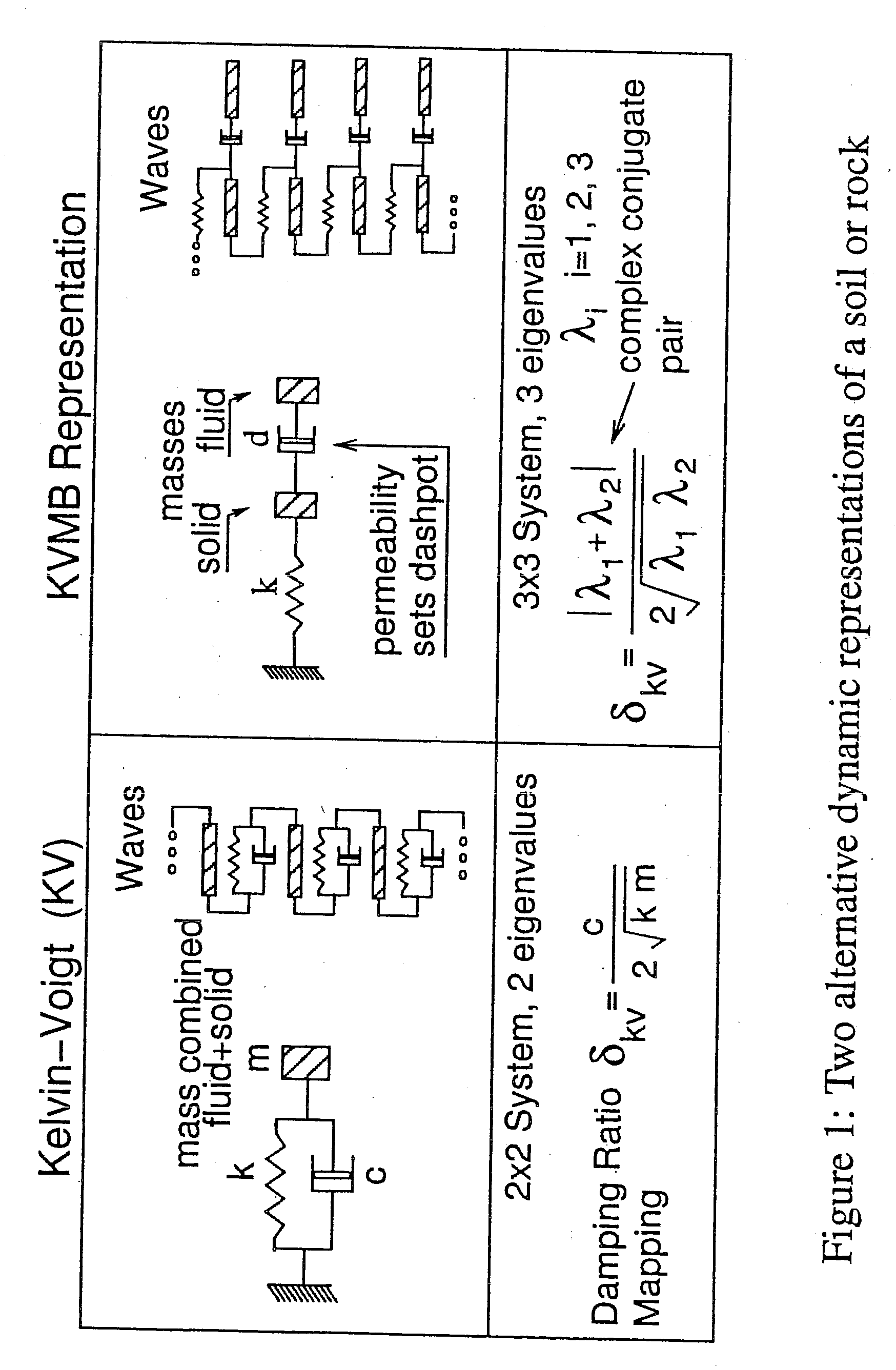
[0134]A method for determining in-situ stiffiness and damping has been presented. The method is to jointly invert both measurements of SH-wave velocity dispersion and spatial amplitude decay, corrected for beam divergence. The method is consistent with current engineering practice and uses a Kelvin / Voigt constitutive model. The field examples presented here demonstrate that the method works in practice. Furthermore, the current use of the Kelvin-Voigt model in engineering (where pore water is present) is supported by these in situ determinations.

[0135]Since damping will increase the wave velocity, it is possible to introduce significant errors by computing shear modulus from wave velocity alone. It has been common practice to compute the shear modulus from measurements of the dominant group velocity of SH-waves. This is like measuring only the resonant frequency in a spring / mass / dashpot experiment, and then computing the spring constant without consideration of any damping effects.

[...

example b

[0180]The following symbols are used in this paper.

[0181]A=cross-sectional area of soil element in thought experiment (m2);

[0182]b=Biot dissipation coefficient (kg / s m3);

[0183]c=dashpot constant for KV model (kg / s);

[0184]d=dashpot constant for KVMB model (kg / s);

[0185]f=friction factor in a cylindrical pore (unitless);

[0186]fn=natural cyclic frequency of soil element (Hz);

[0187]Gf=shear modulus of frame (Pa);

[0188]Gs=specific gravity of soil solids (unitless);

[0189]g=acceleration due to gravity (9.81 m / s2);

[0190]hf=head loss in a cylindrical pore (m);

[0191]Kd=hydraulic conductivity (m / s);

[0192]k=KV spring (N / m);

[0193]k=absolute permeability M2);

[0194]kf=spring constant of frame (N / m);

[0195]L=length of soil element in thought experiment (m);

[0196]m=KV mass (kg);

[0197]mf=frame mass for KVMB model (kg);

[0198]mw=water mass for KVMB model (kg);

[0199]n=porosity (unitless);

[0200]R=Reynolds number for flow in a cylindrical pore (unitless);

[0201]t=time (s);

[0202]u=particle displacement of KV ...


PUM


Abstract

Permeability of a fluid through a saturated material is determined by measuring the dynamic response of that saturated material to shaking vibrations and/or shear wave propagation, and then mapping the dynamic response (preferably, viscoelastic stiffness and damping properties) to an invented model (called “KVMB”) that yields the property of permeability. The preferred embodiments may use shear waves, inertial effects, and/or transmission effects, but preferably not compression, to force fluids through the pores. The mapping preferably predicts two possible mappings to permeability, coupled and uncoupled. The preferred methods are both internally consistent and directly related to known laws of physics rather than dependent on empirical calibrations. In use, for example, one may use a porosity log (conventional neutron or sonic) and recordings of SH-waves to obtain damping ratio, followed by locating of the damping ratio on a KVMB map that depends on porosity, and choosing of one of the two possible permeabilities indicated by the mapping, wherein the best choice is typically the largely coupled case.

Description

[0001]This application claims priority of Provisional Application Ser. No. 60 / 915,346, filed May 1, 2007, and entitled “Determination of Permeability From Damping,” which is hereby incorporated by reference.[0002]Early work on this matter was done with funding from U.S. Army Grant DA AH04-96-1-0318.BACKGROUND OF THE INVENTION[0003]1. Field of the Invention[0004]The invention relates to methods, apparatus, and / or programming code means for determining the permeability of a fluid through a saturated material by measuring the dynamic response of that saturated material to shaking vibrations or shear wave propagation, and mapping data from said dynamic response to an invented alternative constitutive model that yields the property of permeability. Permeability may be described generally as the ease with which fluids can move through rock, soil, or other earth materials, and, therefore, the invented procedures, apparatus, and / or programming code means may be applied in oil well productio...

Claims


Application Information

Patent Timeline
IPC IPC(8): G01N15/08
CPCG01N15/0893G01N15/0826
Inventor MICHAELS, PAUL
Owner BOISE STATE UNIVERSITY
Why Eureka
Try Eureka