One kind of foot pedal hydraulic jack with two speed pump, and there is a pneumatic set to lift piston quickly on the jack

a hydraulic jack and two-speed technology, applied in the direction of fluid couplings, servomotors, couplings, etc., can solve the problems of high fabrication costs, affecting the competitive power of products in international markets, and not being able to meet the functional requirement of quick ascending, etc., to achieve excellent fabricating techniques, simple structural design, and high reliability

Inactive Publication Date: 2009-05-28
CHANGSHU TONGRUN AUTO ACCESSORY
View PDF15 Cites 12 Cited by
  • Summary
  • Abstract
  • Description
  • Claims
  • Application Information

AI Technical Summary

Benefits of technology

[0005]As compared with existing technologies, this invention has the following favorable effects: axes hole of small piston ring of the pump cylinder forms a movable pair with step pump core post section through clearance fit; whereas, the external circle of the small piston ring of the pump cylinder forms a movable pair with pump body hole. Owing to the simple structural design, the pump core step interface used for conversion between quick and slow pump has high reliability, which is characterized by the excellent fabricating technique and low cost. Furthermore, the high-pressure air provided for the pneumatic valve parts of this type of jack can quickly press the hydraulic oil into the chamber of working oil cylinder to realize the quick lift of piston cylinder or rod of the jack under zero or light load, and thus improve the practicability of the product, and enhance its competitive power in the market.

Problems solved by technology

However, it is far from being able to satisfy the functional requirement for quick ascending as required by the hydraulic jack under zero or light load.
As the structural technique of the pump core and pump body is so complicated, the high fabrication cost would affect the competition power of the product in international market.

Method used


Image

  • One kind of foot pedal hydraulic jack with two speed pump, and there is a pneumatic set to lift piston quickly on the jack
  • One kind of foot pedal hydraulic jack with two speed pump, and there is a pneumatic set to lift piston quickly on the jack
  • One kind of foot pedal hydraulic jack with two speed pump, and there is a pneumatic set to lift piston quickly on the jack

Examples


Embodiment Construction

[0019]Further description of this invention in combination with attached drawings for empirical examples is helpful to the understanding of contents and effect of this technology. However, the empirical example will not impose any limitation on technical proposal of this invention.

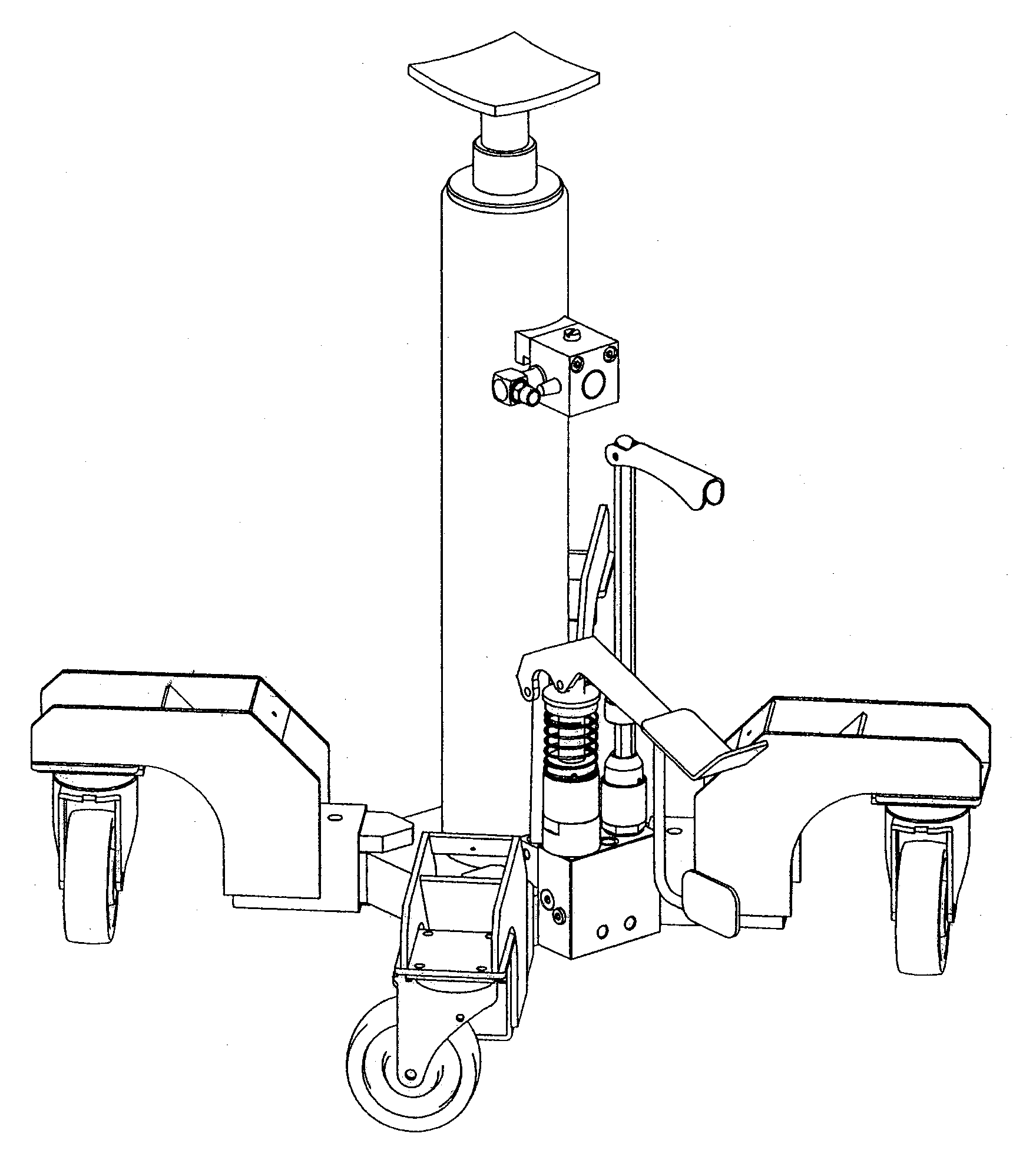
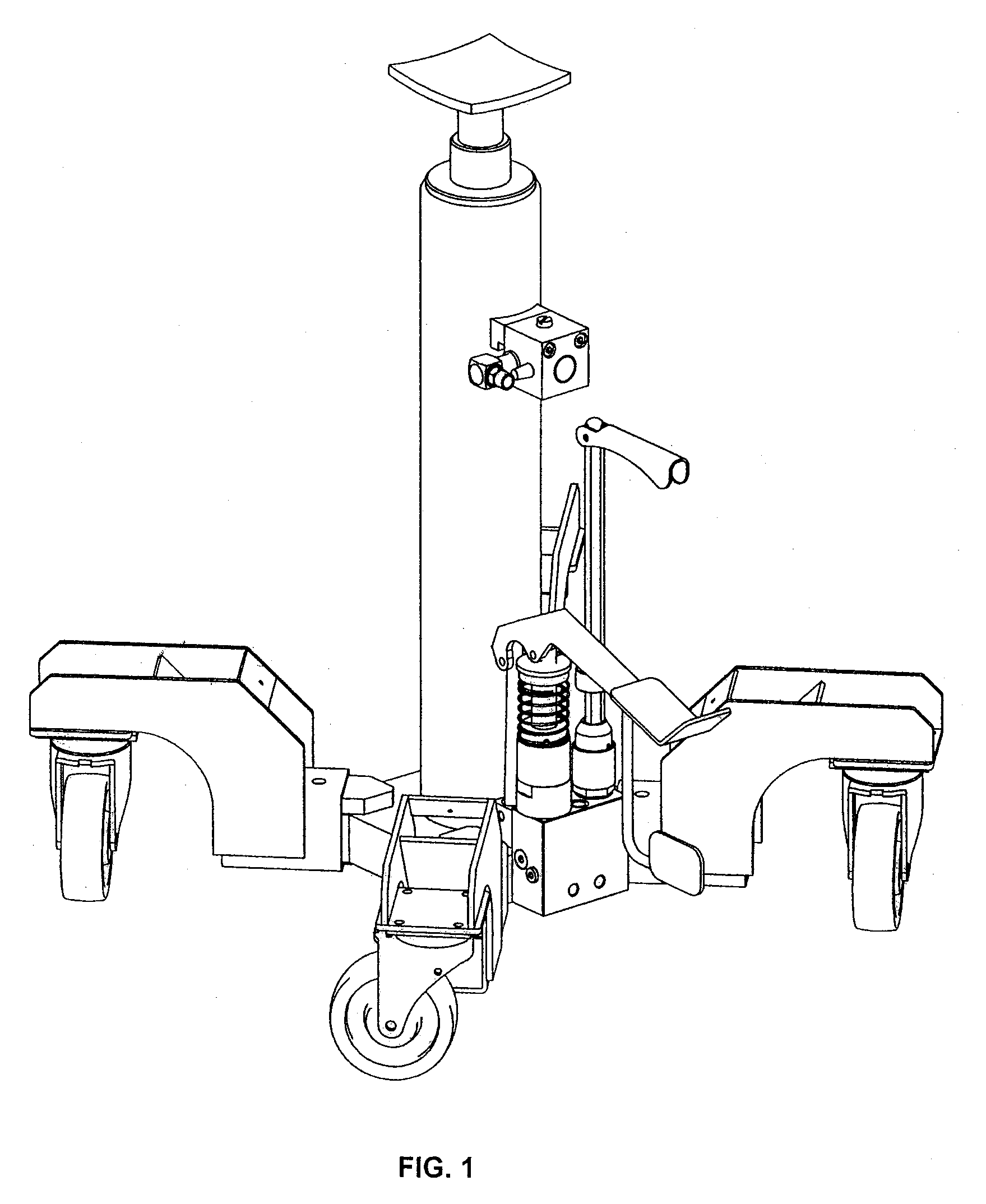
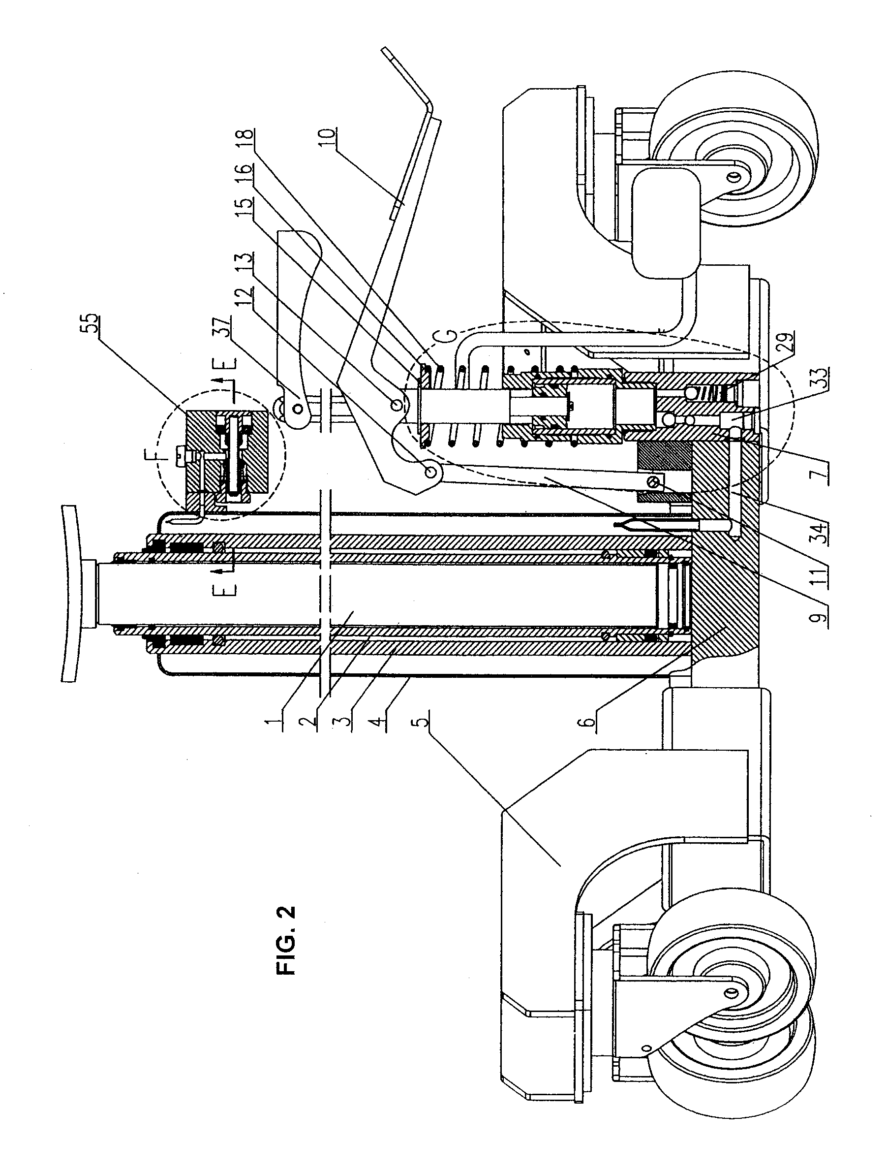
[0020]As indicated in attached drawing, framework part 5 is firmly fixed to base 6; oil cylinder is welded to base 6; upper and lower parts of external sleeve 4 are sealed and welded to oil cylinder 3 and base 6 respectively; piston rod 1 and piston cylinder 2 form a movable assembly through sealing; piston cylinder 2 and oil cylinder 3 form a movable assembly through sealing; pin positioning block of connecting rod 64 is firmly fixed to the valve soleplate 7; base 6 is firmly fixed to the valve soleplate 7, which subjects to the treatment for hydraulic sealing connection at the junction of corresponding oil way; firmly connect the lower fastness set 21 of pump body to the valve soleplate 7 provided with u...


PUM


Abstract

This invention involves a type of pneumatic non-load quick dual-speed hydraulic jack, of which, the small of piston ring (17) of hydraulic pump cylinder integrates with pump body (19) and external ring of step pump core (14) to form movable assembly; the middle part of step pump core (14) is provided with pump core step interface (8); the step hole on the same axis of pneumatic valve block on special pneumatic valve structure is provided with washer (48), button (49), pneumatic valve core (45), compressed spring (68) and valve core securing seat (46). The available effect of this invention is stated as follows: the pump core interface used for conversion of hydraulic speed is characterized by the excellent process and low cost; the pneumatic valve parts specially provided for the jack can replace the hydraulic quick pump structure partially when the high-pressure air source is available. High-pressure air delivered to the oil reservoir of the external sleeve (4) will press the hydraulic oil into the oil chamber of oil cylinder, and thus facilitate the quick lift of jack piston under light load or empty load.

Description

FIELD OF THE INVENTION[0001]This invention involves a type of hoisting tool, especially a type of pneumatic non-load quick dual-speed hydraulic jack.BACKGROUND OF THE INVENTION[0002]Hydraulic jack is a type of hoisting equipment widely applied to lift of vehicles or heavy goods. Existing hydraulic jack normally adopts the dynamic oil cylinder using single-post pump core and pump body hole to realize the clearance fit, which is characterized by simple structure and low technical cost. However, it is far from being able to satisfy the functional requirement for quick ascending as required by the hydraulic jack under zero or light load. As disclosed by Chinese patent ZL200620075069.1, the dual-speed vertical hydraulic jack, oil sucked by the pump core of hydraulic system of zero load or light load under low pressure can be fully pressed into the working oil chamber; whereas, partial oil is pressed into the upper chamber of the pump cylinder when the system is under high pressure. Parti...

Claims


Application Information

Patent Timeline
Patent Type & Authority Applications(United States)
IPC IPC(8): B66F3/42
CPCB66F3/42B66F3/245
Inventor SHI, ZHIGIANG
Owner CHANGSHU TONGRUN AUTO ACCESSORY
Why Eureka
Try Eureka