Controlling power supply to memory cells

a technology of memory cells and power supply, applied in the field of data processing, can solve problems such as the inability to consistently write data values to the cell, and achieve the effect of efficient and effective wri

Active Publication Date: 2009-05-28
ARM LTD
View PDF4 Cites 11 Cited by
  • Summary
  • Abstract
  • Description
  • Claims
  • Application Information

AI Technical Summary

Benefits of technology

[0031]When a data 0 is to be written then the two devices store opposite values to those that they stored for the 1. Thus, controlling the

Problems solved by technology

The traditional six transistor bit cell is widely used for storing data and suffers from the problem of being unable to consistently write data values to

Method used


Image

  • Controlling power supply to memory cells
  • Controlling power supply to memory cells
  • Controlling power supply to memory cells

Examples


Embodiment Construction

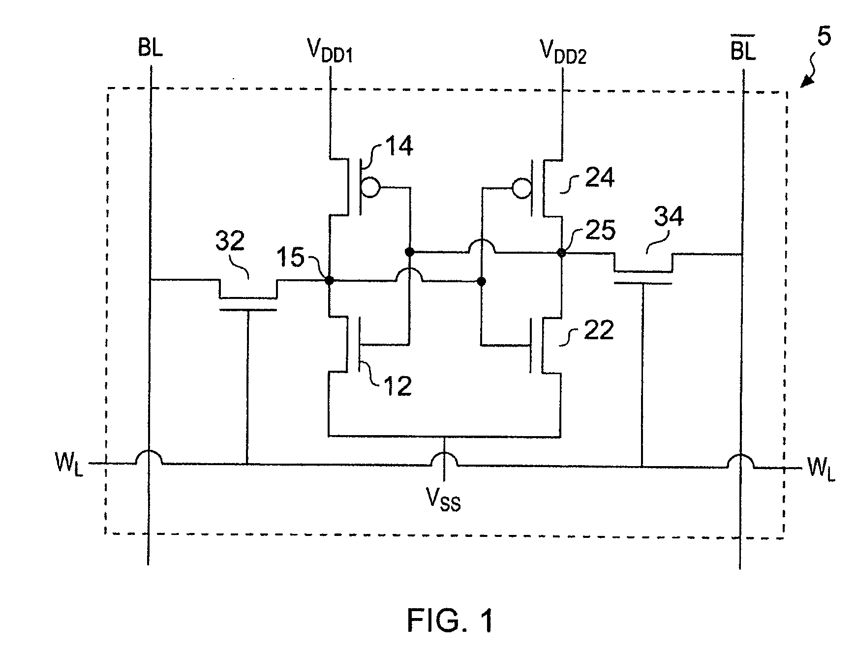
[0046]FIG. 1 illustrates a memory cell 5 according to an embodiment of the present invention. The memory cell 5 comprises a pair of cross-coupled inverters formed by transistors 12, 14, 22 and 24. Transistors 12 and 14 form a first device which is powered by VDD 1 while transistors 22 and 24 form a second device powered by VDD 2. These two devices have a common low voltage rail VSS.

[0047]The memory cell further comprises bit lines BL and a word line WL. The word line is connected to the gates of two access transistors 32 and 34 which when switched on by a signal on this word line provide a path between an input / output portion 15, 25 of the devices and the bit lines. Thus, under control of the word line the devices can be placed in data communication with the bit lines and data can be read in or written out from these devices.

[0048]As the two devices are a cross coupled pair if device 1, transistors 12 and 14 has a 1 at input / output port 15 then second device transistors 22, 24 will ...


PUM


Abstract

A semiconductor memory storage cell and a memory comprising an array of these storage cells is disclosed. The storage cell comprising: a feedback loop comprising two devices for storing opposite binary values; data input and output for inputting data to and outputting data from said two devices; and each of said two devices comprising a power source input, such that each device can be powered independently of the other.

Description

BACKGROUND OF THE INVENTION[0001]1. Field of the Invention[0002]The field of the invention relates to data processing and in particular to memory storage cells.[0003]2. Description of the Prior Art[0004]Memory storage cells formed from semiconductors in integrated circuits are known. They are conventionally formed of bistable circuits that can be flipped between one of two stable states. If the circuits are well balanced then they do not preferentially store either state. A well balanced cell that does not preferentially store a particular value will have the advantage of holding either value with approximately the same power loss and will be as easy to write a “one” to as it is to write a “zero”. However, a potential drawback of such a cell is that on power up it is unknown which value will to be stored in these cells and there are circumstances where it would be advantageous to initialise a memory in a known state.[0005]There is a continual demand to reduce the size and power cons...

Claims


Application Information

Patent Timeline
IPC IPC(8): G11C5/14G11C7/00
CPCG11C5/14
Inventor HOLD, BETINA
Owner ARM LTD
Why Eureka
Try Eureka