

F-type right angle jack
a right angle jack and jack technology, applied in the direction of contact member manufacturing, coupling device connection, two-pole connection, etc., can solve the problems of poor contact, low quality of signal transmission, high cost of valuable molds, etc., to reduce manufacturing costs, improve transmission quality, and reduce signal transmission loss
Inactive Publication Date: 2009-05-28
GOU PONY
View PDF13 Cites 24 Cited by
- Summary
- Abstract
- Description
- Claims
- Application Information
AI Technical Summary
Benefits of technology
[0007]The present invention is to provide a tap assembly made through simplified steps, signal loss ratio of the finished tap assembly also can be reduced.
Problems solved by technology
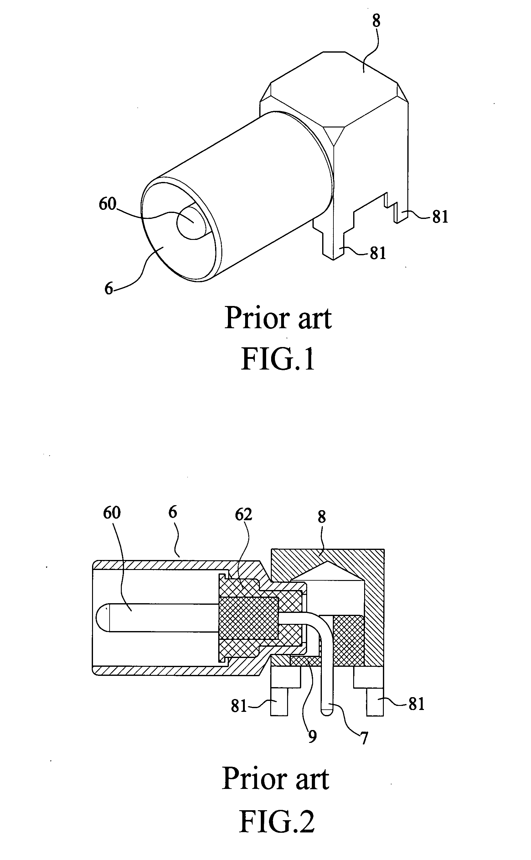
1. The squarish housing (8) made of metal is shaped by molding cast, and the bayonet mount (6) is riveted to the housing by riveting. In manufacturing, it needs more steps to finish the F-type right angle jack.
2. Right angle connector (7) disposed inside a hollowed out metal housing (8). But the right angle connector (7) is connected to the squarish housing by only two “anchor” points between curved segments. It leads to poor contact. Quality of signal transmission is lowered.
3. The bayonet mount (6) is riveted to the housing (8) by riveting. The housing (8) needs interior hardness and surface evenness evenly formed to process with the bayonet mount. The housing (8) is preferably shaped in cast molding, not only valuable molds are expensive, but more raw materials be wasted in manufacturing.
Method used
View moreImage
Smart ImageViewing Examples

Examples
first embodiment
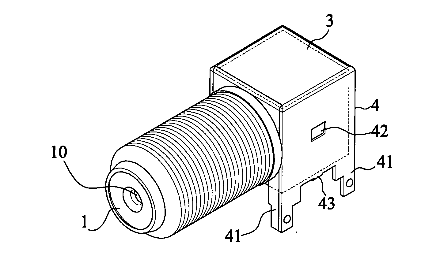
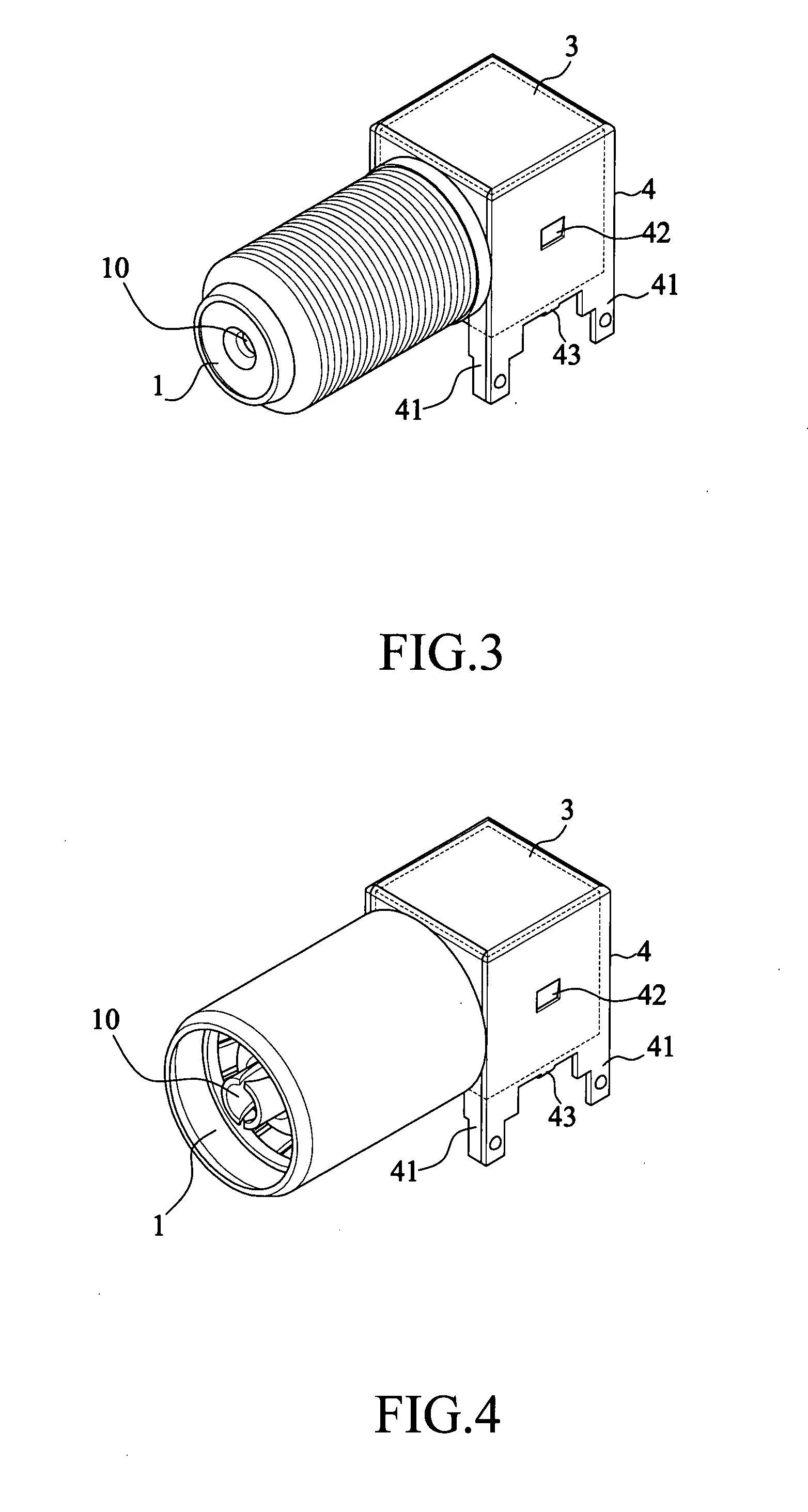
[0028]FIG. 3: shows a schematic view of a female F-type right angle jack of the present invention.
second embodiment
[0029]FIG. 4: shows a schematic view of a female F-type right angle jack of the present invention.
third embodiment
[0030]FIG. 5: shows a schematic view of a male F-type right angle jack of the present invention.
[0031]FIG. 6: shows a sectional view of FIG. 5.
[0032]FIG. 7: shows an exploded view of FIG. 5.
[0033]FIG. 8: shows a diagrammatic view of manufacturing process of the invention.
[0034]FIG. 9: shows a schematic view of manufacturing process of the invention.
Login to View More PUM
 Abstract
F-type right angle jack of tap assembly manufactured in a few steps lowering signal loss ratio comprises a bayonet mount, a male connector axially disposed inside the bayonet mount, a right angle connector is in-line coupled to the male connector, a cubic coupling box, corner legs of a metallic frame inserted onto printed circuit board (PCB). The coupling box is directly formed between the bayonet mount and the male connector by injection molding. The coupling box wraps around a tapered tube of the bayonet mount filled with insulation material. A joint of the right angle connector and the male connector is wrapped around by the coupling box, but a proximal end of the right angle connector is exposed outside the coupling box. And a metallic frame squarish in shape formed by stamping and bending is wrapped around the coupling box to facilitate coaxial cable carries signals without loss.
Description
FIELD OF THE INVENTION[0001]The present invention is related to an F-type right angle jack of tap assembly for transmission television (TV) or cable antenna television (CATV) signals applicable to analog television system such as National Television System Committee (NTSC), international electronic commission (IEC), phase alternating line (PAL), Séquentiel couleur á mémoire (SECAM), and manufacturing method of the same.DESCRIPTION OF PRIOR ARTS[0002]As shown in FIGS. 1 and 2, a conventional tap assembly comprising an F-type right angle jack (or BNC-bayonet Neill-Concelman connector—right angle jack) fixed to a printed circuit board (PCB)—such a connector placed on coaxial cables that would minimize wave reflection / loss—for transmitting TV or CATV signals, it includes a bayonet mount (6) riveted to a lateral side of a squarish housing (8), wherein the bayonet mount (6) has a housing made of metal surrounding a male connector (60) can be used as grounding. The male connector (60) is a...
Claims
Login to View More Application Information
Patent Timeline
 IPC IPC(8): H01R12/00
CPCH01R24/50H01R43/16H01R2201/18H01R2103/00H01R2201/02H01R43/205
InventorGOU, PONY
OwnerGOU PONY