Floating floor assembled from an array of interconnected subunits, each of which includes a stone, ceramic, or porcelain tile bonded to an injection molded polyolefin substrate

a technology of interconnected subunits and floating floors, applied in the field of floating floors and tile floors, can solve the problems of difficult sealing or bonding of materials with adhesives, and the difficulty of adhesive bonding to those materials

Inactive Publication Date: 2009-06-04
RITTER CARR & ASSOC
View PDF15 Cites 47 Cited by
  • Summary
  • Abstract
  • Description
  • Claims
  • Application Information

AI Technical Summary

Benefits of technology

[0014]As a consequence of the low-energy characteristics of polyolefin thermoplastic materials, the bonding surface of each of the substrates is treated by oxidation, plasma, corona, flame, or sprayed with a high-surface-energy primer prior to the application of an adhesive layer to the surface and positioning of a tile on top of the adhesive layer. It has been determined that the use of epoxy adhesive, such as IT Devcon® two-part epoxy, applied after flame treatment of the upper surface, works well.

Problems solved by technology

The toughness, rigidity, room-temperature resistance to chemicals, and abrasion resistance of certain polyolefin polymers that make them ideal materials for floor tiles also make adhesive bonding to those materials difficult.
It is difficult to seal or bond such materials using commonly available sealant adhesives.

Method used


Image

  • Floating floor assembled from an array of interconnected subunits, each of which includes a stone, ceramic, or porcelain tile bonded to an injection molded polyolefin substrate
  • Floating floor assembled from an array of interconnected subunits, each of which includes a stone, ceramic, or porcelain tile bonded to an injection molded polyolefin substrate
  • Floating floor assembled from an array of interconnected subunits, each of which includes a stone, ceramic, or porcelain tile bonded to an injection molded polyolefin substrate

Examples


Embodiment Construction

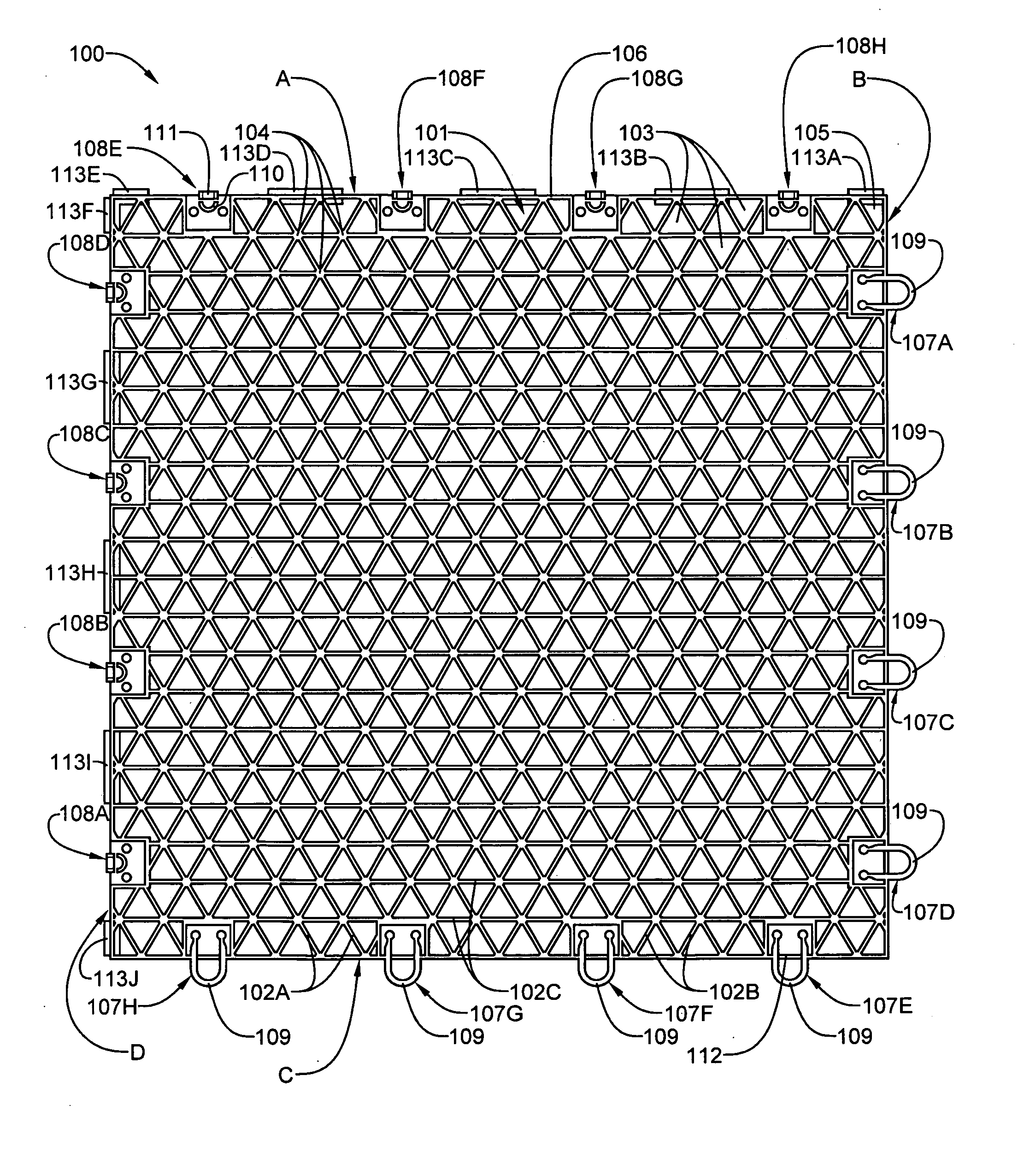
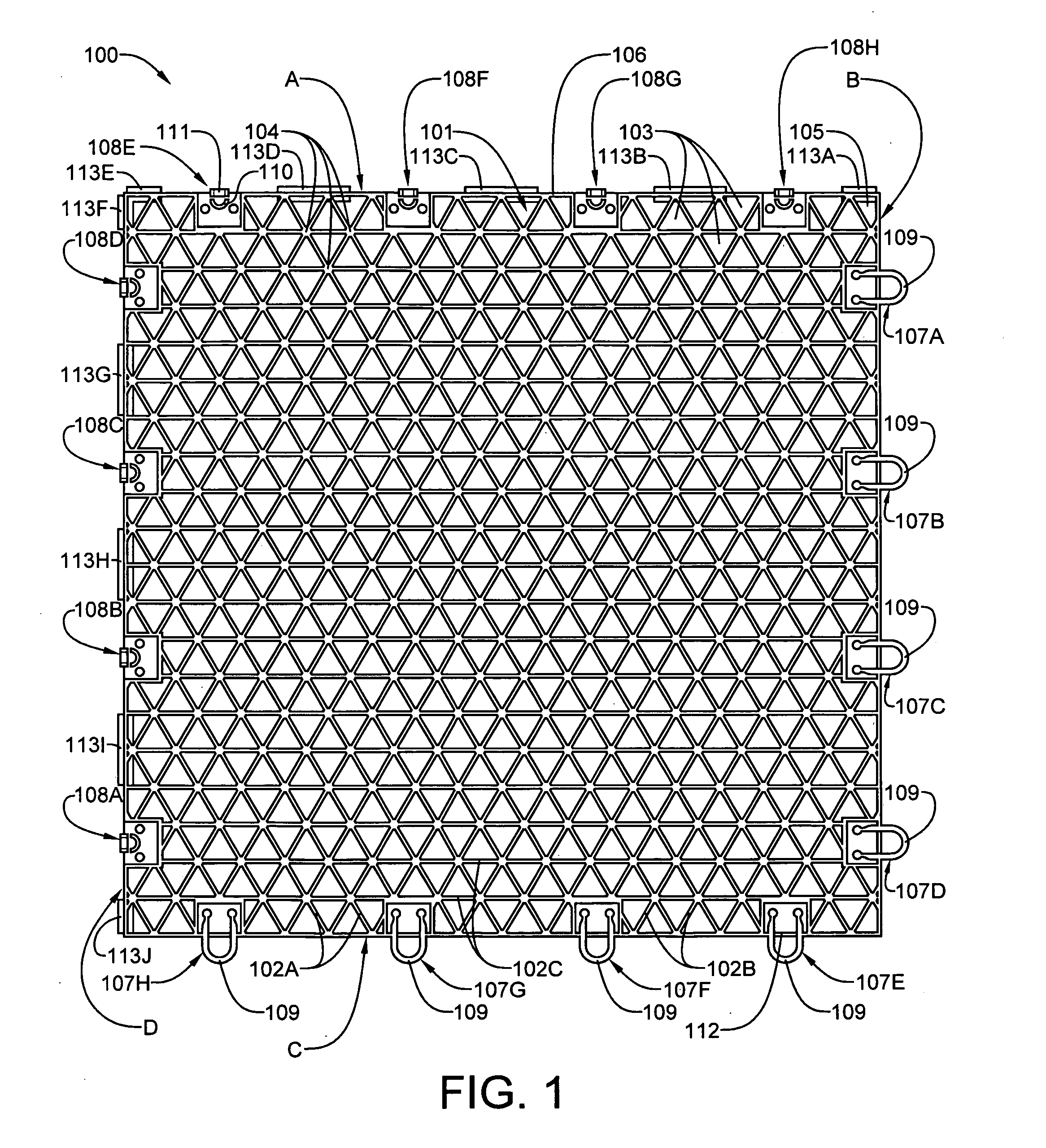
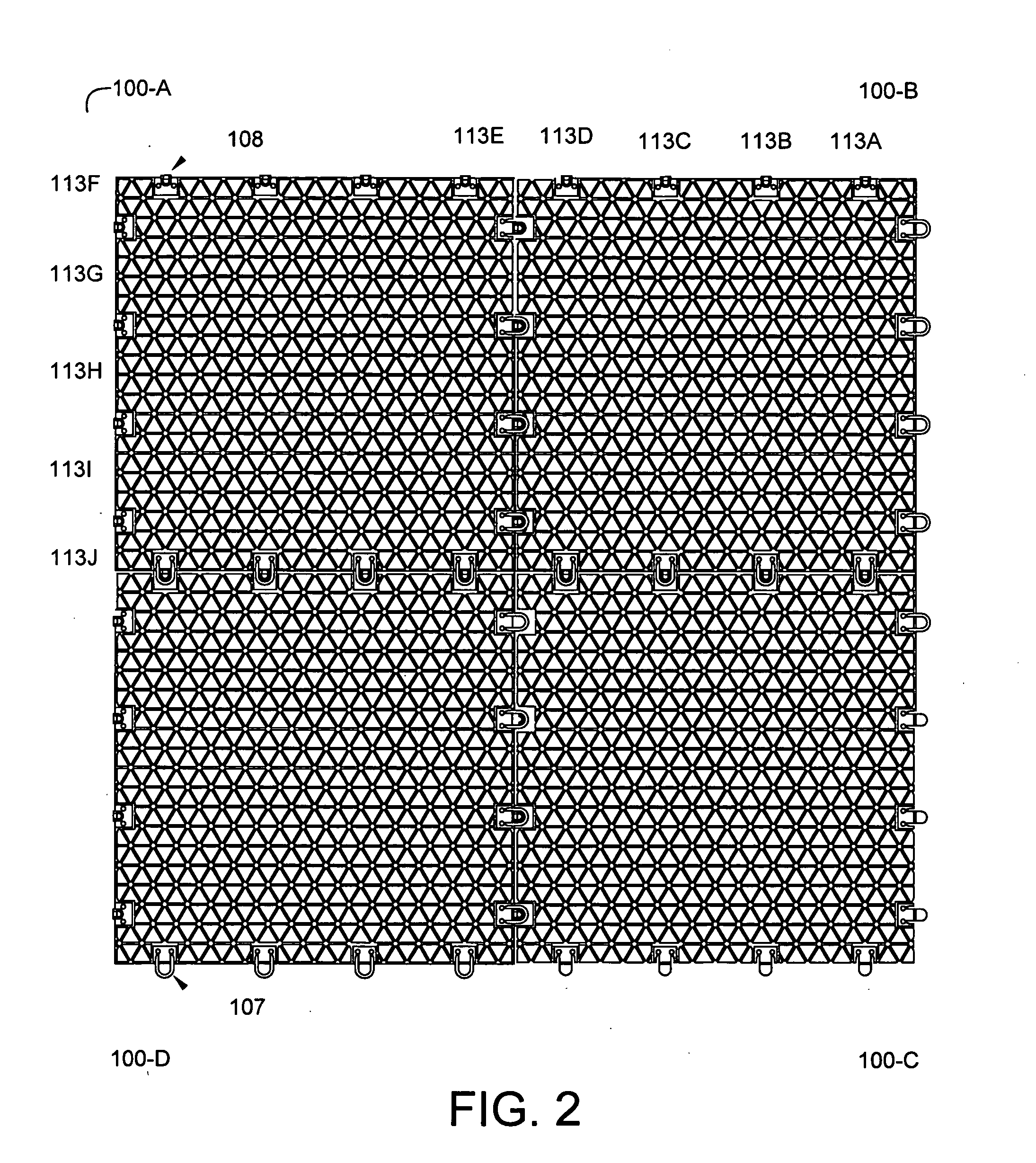
[0033]The invention will now be described with reference to the attached drawing figures. It should be understood that the drawings are not necessarily drawn to scale and are meant to be merely illustrative of the invention. The invention may be practiced using tiles of different shapes, including those having rectangular and hexagonal configurations. FIGS. 1 through 6 disclose the manufacture and assembly of tiles having a rectangular configuration. FIGS. 7 through 12 disclose the manufacture and assembly of tiles having a hexagonal configuration.

[0034]Referring now to FIG. 1, a square polymeric plastic substrate 100, fabricated in accordance with the present invention, is sized to accommodate the attachment on an upper surface thereof of a square stone, ceramic or porcelain tile. The substrate 100 is injection molded as a single piece thermoplastic material having the characteristics of exceptional toughness, stress-crack resistance, chemical resistance, and stiffness. Although th...


PUM

PropertyMeasurementUnit
thickaaaaaaaaaa
heightaaaaaaaaaa
thickaaaaaaaaaa

Abstract

A floating floor assembled from an array of interconnected subunits, each of which includes a stone, ceramic or porcelain tile and a one-piece polymeric plastic substrate to which the stone, ceramic, or porcelain tile is bonded. Each substrate is injection molded from certain polyolefin polymers and incorporates the interlock structure and certain other features of the modular sports tiles of U.S. Pat. No. 4,930,286. The substrates of the present invention, however, differ in that each substrate incorporates a vertical stabilization system, the plastic support grid is formed by three sets of mutually intersecting walls, with each set being angularly offset from the other two by 120 degrees, and each substrate is sized to precisely fit a stone, ceramic or porcelain tile, which is accurately positioned by tile locator tabs on a pair of intersecting sides of the substrate.

Description

PRIORITY DATA [0001]This application has a claim of priority based on the filing of non-provisional utility patent application Ser. No. 11 / 947,837, of the same title, and by the same inventor on Nov. 30, 2007.BACKGROUND OF THE INVENTION[0002]1. Field of the Invention[0003]The present invention relates to floating floors, tile floors and, more particularly, to floating floors assembled from an array of interconnected subunits, each of which includes a ceramic or stone tile bonded to an injection molded plastic substrate, as well as to a method for manufacturing such subunits.[0004]2. Description of the Prior Art[0005]Several attempts have been made in recent years to create floating floors using ceramic tile as the wearing surface. The applicant is aware that, for a short time, a number of U.S. flooring distributors sold boxes of ceramic tile flooring which interlocked to form a floating tile floor. The tiles were mounted on laminate flooring substrates. However, after consumers expe...

Claims


Application Information

Patent Timeline
Patent Type & Authority Applications(United States)
IPC IPC(8): E04F15/10
CPCB32B3/10Y10T428/16B32B9/002B32B9/005B32B9/045B32B27/32B32B3/06B32B3/12B32B2255/10B32B2255/26B32B2307/546B32B2307/558B32B2307/7265B32B2307/746B32B2419/04Y10T428/19E04F15/18E04F15/02194E04F15/087E04F15/105
Inventor HILL, DAVID TILGHMAN
Owner RITTER CARR & ASSOC
Why Eureka
Try Eureka