Igniter system

a technology of ignition system and ignition chamber, which is applied in the direction of machines/engines, induction energy storage installations, other installations, etc., can solve the problems catalyst no longer succeeding ignition, etc., to prevent increase the reliability of the igniter system, and prevent the effect of catalyst melting or deterioration

Inactive Publication Date: 2009-06-04
FUJI ELECTRIC CO LTD
View PDF9 Cites 23 Cited by
  • Summary
  • Abstract
  • Description
  • Claims
  • Application Information

AI Technical Summary

Benefits of technology

[0014]The present invention is directed to solving the above-described problem, and thereby providing an igniter system that is increased in reliability by preventing misfires and melting or deterioration of the catalyst due to a coil failure.
[0028]According to the invention, a coil failure detection circuit is additionally provided in the power IC, whereby a coil failure is detected, a fail signal is transmitted to an ECU, and an IGBT is turned off to shut off a coil current and prevent misfires. At the same time, the flow of unburned gas (fuel) is shut off, whereby the time when a catalyst is exposed to unburned gas is shortened and melting or deterioration of the catalyst is prevented. As a result, the reliability of the igniter system can be increased.
[0029]A dv / dt detection circuit for detecting the slope of a turn-off voltage of the IGBT is provided in the ECU, whereby a coil failure is detected and the IGBT is turned off to shut off a coil current and prevent misfires. At the same time, the flow of unburned gas is shut off, whereby the time when a catalyst is exposed to unburned gas is shortened and melting or deterioration of the catalyst is prevented. As a result, the reliability of the igniter system can be increased.

Problems solved by technology

If a coil failure occurs, ignition may fail to cause misfires.
The temperature of the catalyst increases rapidly, as a result of which the catalyst is melted or deteriorated.
Once the catalyst is melted or deteriorated, ignition no longer succeeds.
The coil layer short-circuiting is a phenomenon that the coating of a coil wire that is wound in layers is damaged locally to cause contact between portions of the coil wire.

Method used


Image

  • Igniter system
  • Igniter system
  • Igniter system

Examples


embodiment 1

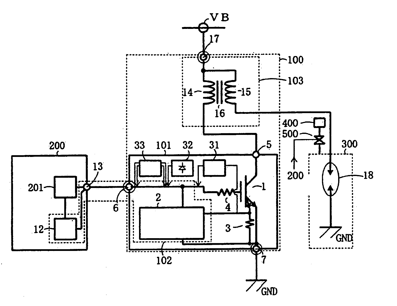
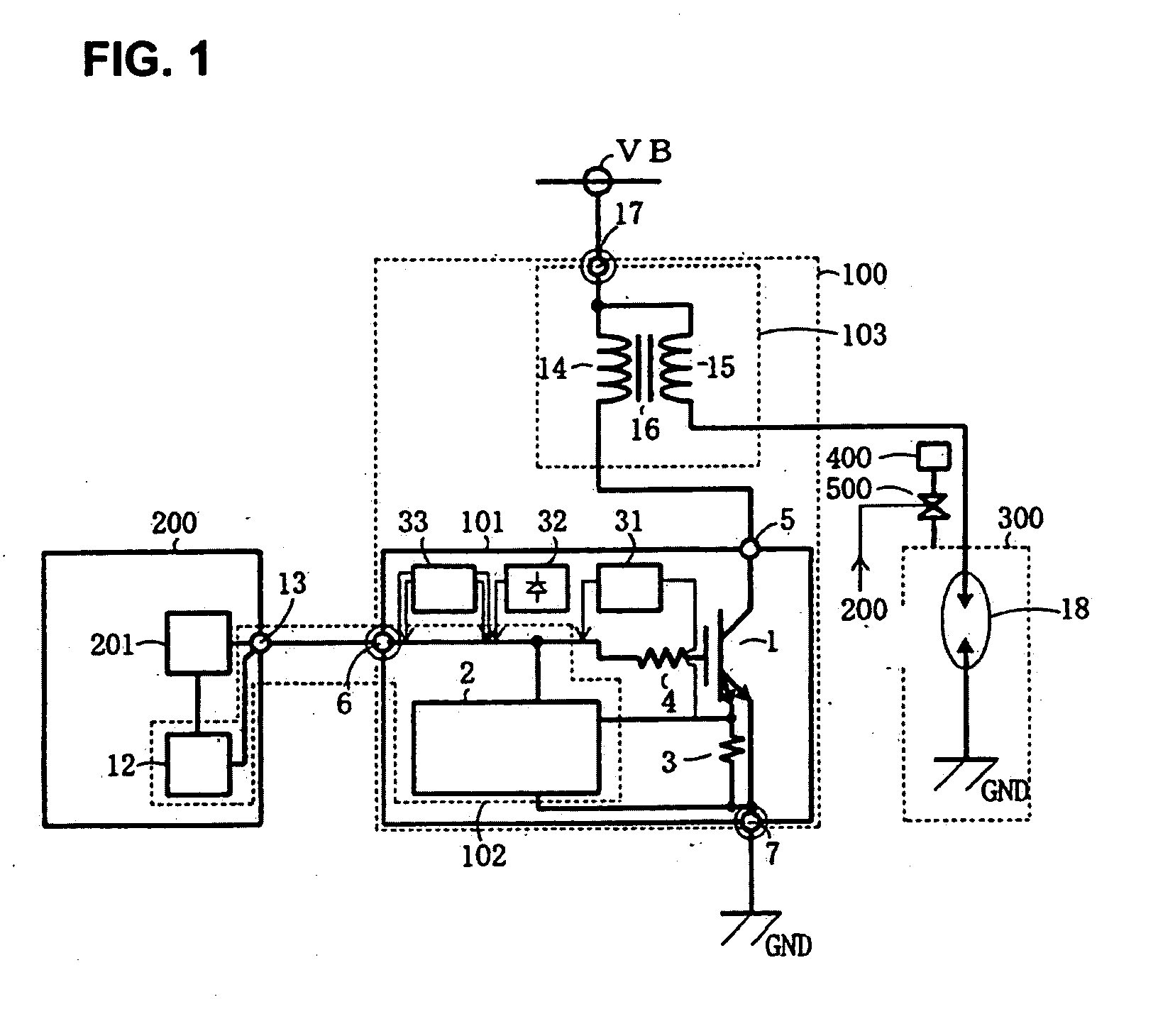
[0044]FIG. 1 is a block circuit diagram of an igniter system according to a first embodiment of the invention. The igniter system according to the first embodiment is composed of an ignition device 100 for an internal combustion engine which consists of a power IC 101 and an ignition coil 103, a combustion chamber 300 having an ignition plug 18, and an ECU 200. The power IC 101 is configured in such a manner that an IGBT 1, various protection circuits (current limiting circuit 31, overheat detection circuit 32, and self-shutoff circuit 33), and a coil failure detection circuit 2 are formed on the same semiconductor substrate.

[0045]A gate drive circuit 201 and a timer circuit 12 are formed in the ECU 200. The coil failure detection circuit 2 and the timer circuit 12 constitute a coil failure judgment circuit 102. An overvoltage prevention circuit etc. (not shown) are also formed in the power IC 101. The power IC 101 is integrated with the ignition coil 103 and they constitute the ign...

embodiment 2

[0061]FIGS. 3A-3C illustrate an igniter system according to a second embodiment of the invention. FIG. 3A is a block circuit diagram of the igniter system, FIG. 3B is a timing chart, and FIG. 3C is a waveform comparison diagram. The third embodiment is directed to a case that a function of detecting a coil failure is provided in the ECU 200.

[0062]The second embodiment is of a voltage detection type and is of a type that a turn-off collector voltage is output to the ECU 200 as it is. The ECU 200 directly detects an abnormality in the manner of rise of a collector voltage if it occurs. A dv / dt detection circuit 19 for detecting an increase rate dv / dt of the collector voltage v and a timer circuit 12 which judges whether a coil abnormality has occurred in response to a signal that is supplied from a dv / dt detection circuit are provided in the ECU 200.

[0063]When a coil abnormality has occurred, the coil inductance is varied and the increase rate dv / dt of the turn-off collector voltage i...

embodiment 3

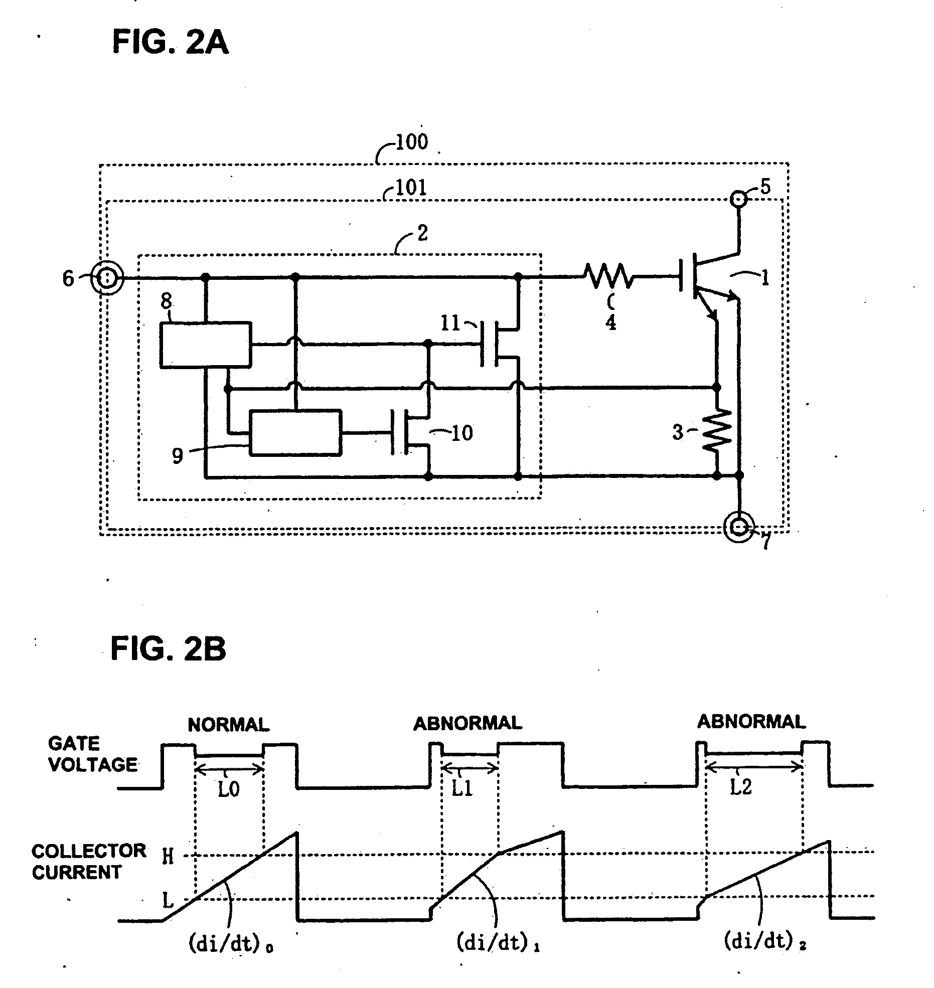
[0070]FIGS. 4A and 4B illustrate an igniter system according to a third embodiment of the invention. FIG. 4A is a block circuit diagram of an IGBT 1 and a coil failure detection circuit 2, and FIG. 4B is a timing chart. The circuit of FIG. 4B is different from that of FIG. 2A in that the voltage that is applied to the L current detection circuit 8 and the H current detection circuit 9 is supplied from a Vcc terminal 21 which is a power supply terminal rather than from the gate terminal 6. The timing chart of FIG. 4B will not be described because it is the same as FIG. 1B. In this scheme, since the Vcc terminal 21 is necessary, the power IC 101 has four terminals, that is, the collector terminal 5, the gate terminal 6, the emitter terminal 7, and the Vcc terminal 21. And the ignition device 100 which incorporates the power IC 101 has four terminals, that is, the VB terminal 17, the gate terminal 6, the emitter terminal 7, and the Vcc terminal 21.


PUM


Abstract

A coil failure detection circuit detects a rise of a collector current of an IGBT and a timer circuit measures the length of a rise period. If the rise is not a normal one, an electronic control unit judges that a coil failure has occurred. The electronic control unit turns off the IGBT to prevent misfires and stops a flow of fuel gas to a combustion chamber to prevent melting or deterioration of a catalyst.

Description

BACKGROUND[0001]The present invention relates to an igniter system using a power IC which incorporates a vertical power semiconductor device.[0002]FIG. 12 is a block circuit diagram of a conventional igniter system that includes an IGBT 1 (insulated-gate bipolar transistor) as a switching element; a current detection resistor 3 which is connected to a current detection emitter terminal (sense emitter terminal) of the IGBT 1; a gate resistor 4 for the IGBT 1; a current limiting circuit 31; an overheat detection circuit 32; and a self-shutoff circuit 33. The operations of the current limiting circuit 31, the overheat detection circuit 32, and the self-shutoff circuit 33 will be described later. The IGBT 1 and protection circuits such as the current limiting circuit 31, the overheat detection circuit 32, and the self-shutoff circuit 33 are formed on the same semiconductor substrate and constitute a power IC 101.[0003]The power IC 101 is combined with an ignition coil 103 to constitute ...

Claims


Application Information

Patent Timeline
Patent Type & Authority Applications(United States)
IPC IPC(8): F02P3/05
CPCF02P3/0552
Inventor NAITO, TATSUYAISHII, KENICHIMIYAZAWA, SHIGEMISAITOU, RYUU
Owner FUJI ELECTRIC CO LTD
Why Eureka
Try Eureka