Apparatus and method for controlling roller mills

Inactive Publication Date: 2009-06-04
OCRIM
View PDF5 Cites 5 Cited by
  • Summary
  • Abstract
  • Description
  • Claims
  • Application Information

AI Technical Summary

Benefits of technology

[0036]Another object of the present invention is to provide an apparatus which, by virtue of its particular

Problems solved by technology

The dielectric constant of the product affects the measurement and the variations of this dielectric constant, which in turn is influenced by temperature and humidity, entail unwanted variations in the measurement.
Therefore, the value of the reference capacitor detected with the constantly immersed probe varies according to the level of the product, thwarting the advantages that would be obtainable with the two-probe system.
The prior art systems described above perform fairly well but in any case do not allow to overcome some drawbacks which typically occur in the plants being considered.
For example, the main difficulty that the testing engineer of milling systems encounters during first starts, is the initial calibration of the adjustment system, whichever it may be.
An incorrect calibration of the systems for adjusting the supply of any milling passage can cause halting of the plant, which is obviously undesirable even during testing.
Also, once the steps for testing the system have been passed, the prior art systems cited above for adjusting the supply of mills, do not allow to cope in a fully reliable manner with some drawbacks that typically occur during steady-state operation, i.e., during normal production steps.
Because of the presence of the clogging sensors in the plant, as mentioned earlier, incorrect calibrations can cause stops, with obvious economic damage.
Since the setting operations are performed manually, it is also not possible to exclude problems that arise from human errors.

Method used


Image

  • Apparatus and method for controlling roller mills
  • Apparatus and method for controlling roller mills
  • Apparatus and method for controlling roller mills

Examples


Embodiment Construction

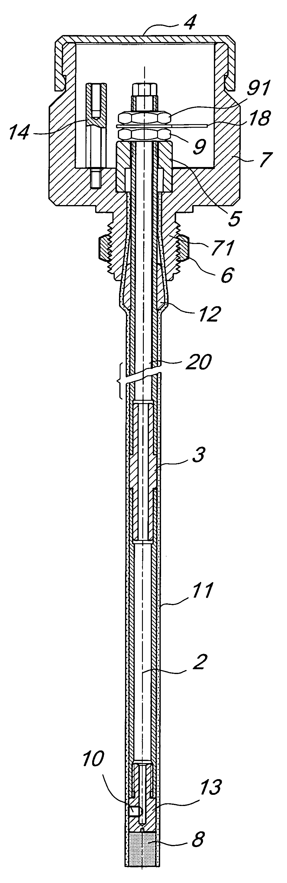
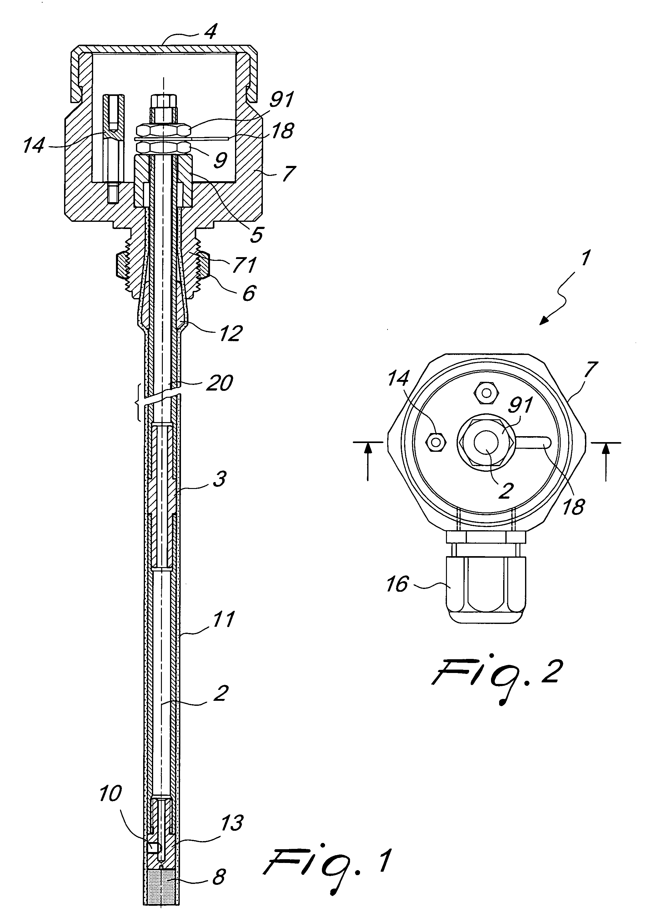
[0047]With reference to the cited figures, the apparatus according to the invention comprises a probe device, generally designated by the reference numeral 1, which is constituted by a first level probe 20 and by a second reference probe 2, which are fitted within a supporting tube 11 with the interposition of an intermediate spacer 3.

[0048]The supporting tube 11 is associated with a casing 7 by means of a conical member 12, which is interposed between the tube 11 and the first probe 20 at a collar 71 of the casing 7.

[0049]The collar 71 is threaded in order to engage a lock nut 6, which locks the tube 11, and therefore the probe assembly, on the bell of the mill.

[0050]The first probe 20 lies inside the casing 7, where it is locked by a first nut 9 with the interposition of an insulating washer 5.

[0051]A second nut 91 locks a connector 18 on the first nut 9.

[0052]A second connector 14, provided with a spacer, is fixed within the casing 7.

[0053]The casing 7 is also provided with a lid...


PUM


Abstract

A control apparatus, particularly for roller mills in plants for milling food products, including a probe device which is inserted in a container of a product to be fed to a pair of milling rollers by feed rollers. The device includes a reference probe, which is always immersed in the product and measures a reference capacitance value, and a level probe, which measures a variation of the capacitance of the product related to the variation of the level of the product. The reference capacitance value and the capacitance variation are used by a control means to actuate the rollers. The probe device is pre-calibrated in factory so as to be able to adapt automatically to the variations of the characteristics of the product to be fed to the rollers.

Description

BACKGROUND OF THE INVENTION[0001]1. Field of the Invention[0002]The present invention relates to an apparatus and a method for controlling roller mills.[0003]Mills for processing cereals to obtain finished products, such as flour, meal and bran, are industrial plants with a high degree of automation, in which various operations are performed for product processing, conditioning, cleaning, milling, screening, by various machines controlled according to clearly defined process patterns or diagrams.[0004]One of the crucial phases of the process is milling, i.e., the gradual reduction of the particle size distribution of the initial cereal, which is performed in roller mills.[0005]Those machines, which are therefore among the most important ones present in a mill, are installed in quantities which can vary typically from 4-5 to 10-20 units, as a function of the total capacity of the system and of the type of cereal processed.[0006]In each individual half-machine, usually known as “passa...

Claims


Application Information

Patent Timeline
IPC IPC(8): B02B5/02B02C7/14B02C9/04
CPCB02C4/286G01F25/0061G01F23/268G01F23/266G01F25/20
Inventor BONELLI, ALBERTO C.TRIACHINI, GIANSANTE O.
Owner OCRIM
Why Eureka
Try Eureka