High-temperature electrostatic transducers and fabrication method

a transducer and high-temperature technology, applied in the field of electrostatic transducers, can solve the problems of significant degrading of transducer sensitivity, the limiting factor of the insulation structure/layer, and the likelihood of an electrical breakdown of the insulation structure,

Inactive Publication Date: 2009-06-04
THE BOARD OF TRUSTEES OF THE LELAND STANFORD JUNIOR UNIV
View PDF1 Cites 30 Cited by
  • Summary
  • Abstract
  • Description
  • Claims
  • Application Information

AI Technical Summary

Problems solved by technology

In state-of-the-art transducers, such as capacitive micromachined ultrasonic transducers (CMUTs), this insulating structure / layer is the main limiting factor in terms of device operation at high temperatures.
The likelihood of an electrical breakdown of the insulation structure is dramatically increased at elevated temperatures.
Further, parasitic capacitance in the insulation layer will significantly degrade the transducer sensitivity at elevated temperatures due to an increased mobility of trapped charges, for example alkali ions in silicon dioxide, and bias-temperature (BT) stress.
Another main limiting factor for high-temperature operation are thermal-expansion related stress effects, when the electrostatic transducer is exposed to high temperatures.
Current fabrication methods leave the CMUT cell unprotected during the fabrication process, resulting in contamination of the cell cavity.
Current CMUT cells do not that have thick insulation layers that are independent from the cavity height, which limits their high temperature and performance.

Method used


Image

  • High-temperature electrostatic transducers and fabrication method
  • High-temperature electrostatic transducers and fabrication method
  • High-temperature electrostatic transducers and fabrication method

Examples


Embodiment Construction

[0053]Although the following detailed description contains many specifics for the purposes of illustration, anyone of ordinary skill in the art will readily appreciate that many variations and alterations to the following exemplary details are within the scope of the invention. Accordingly, the following preferred embodiment of the invention is set forth without any loss of generality to, and without imposing limitations upon, the claimed invention.

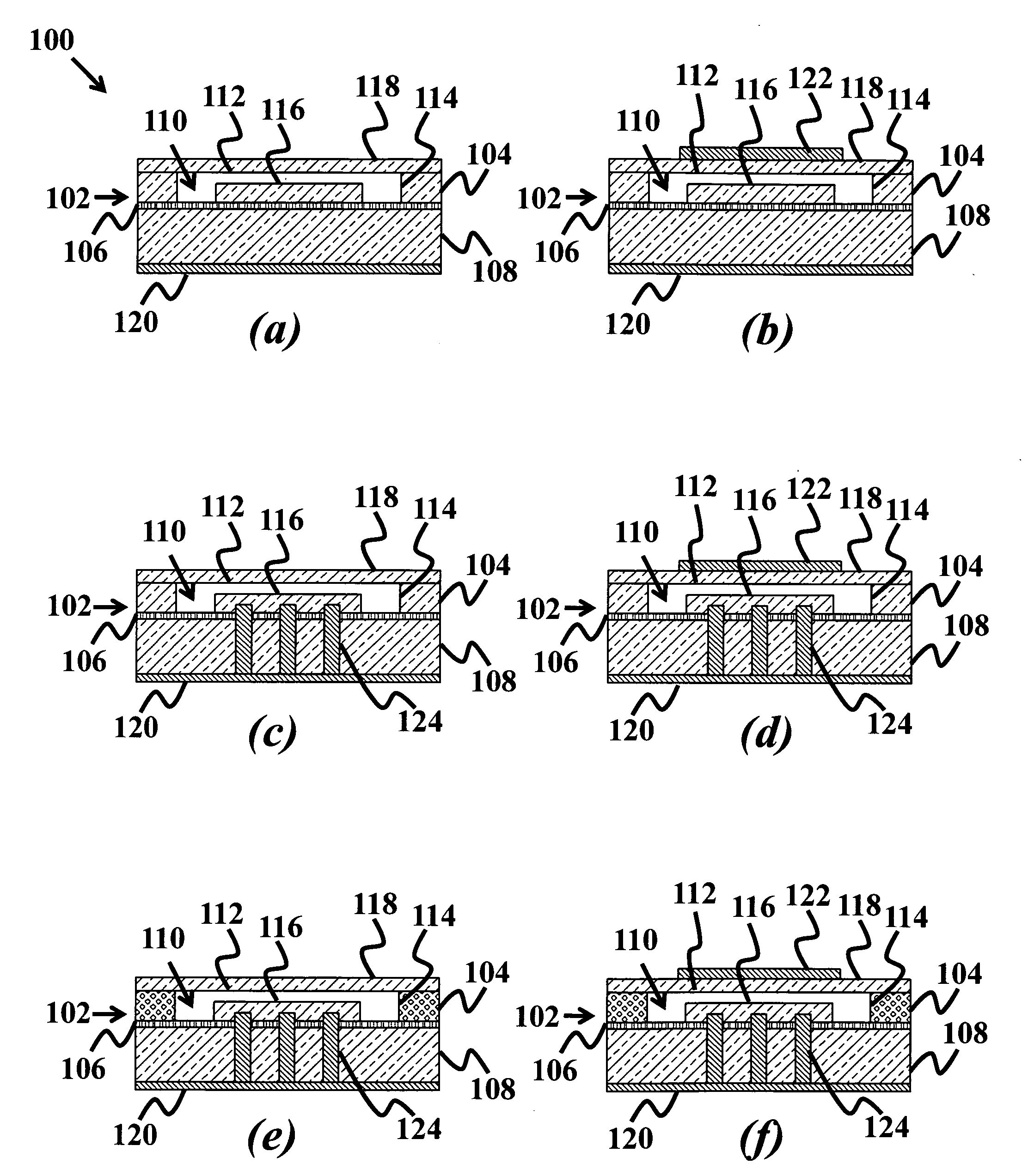
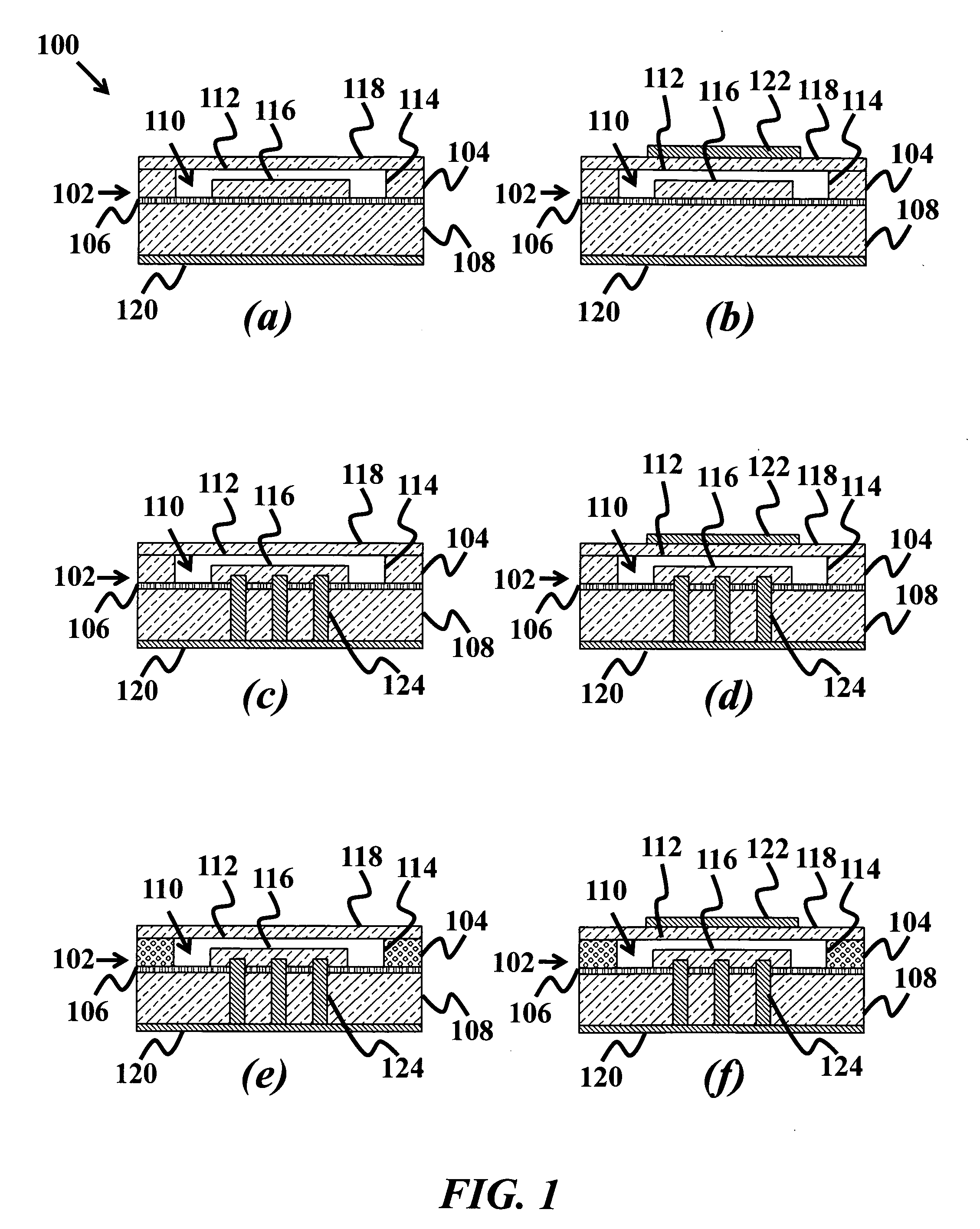
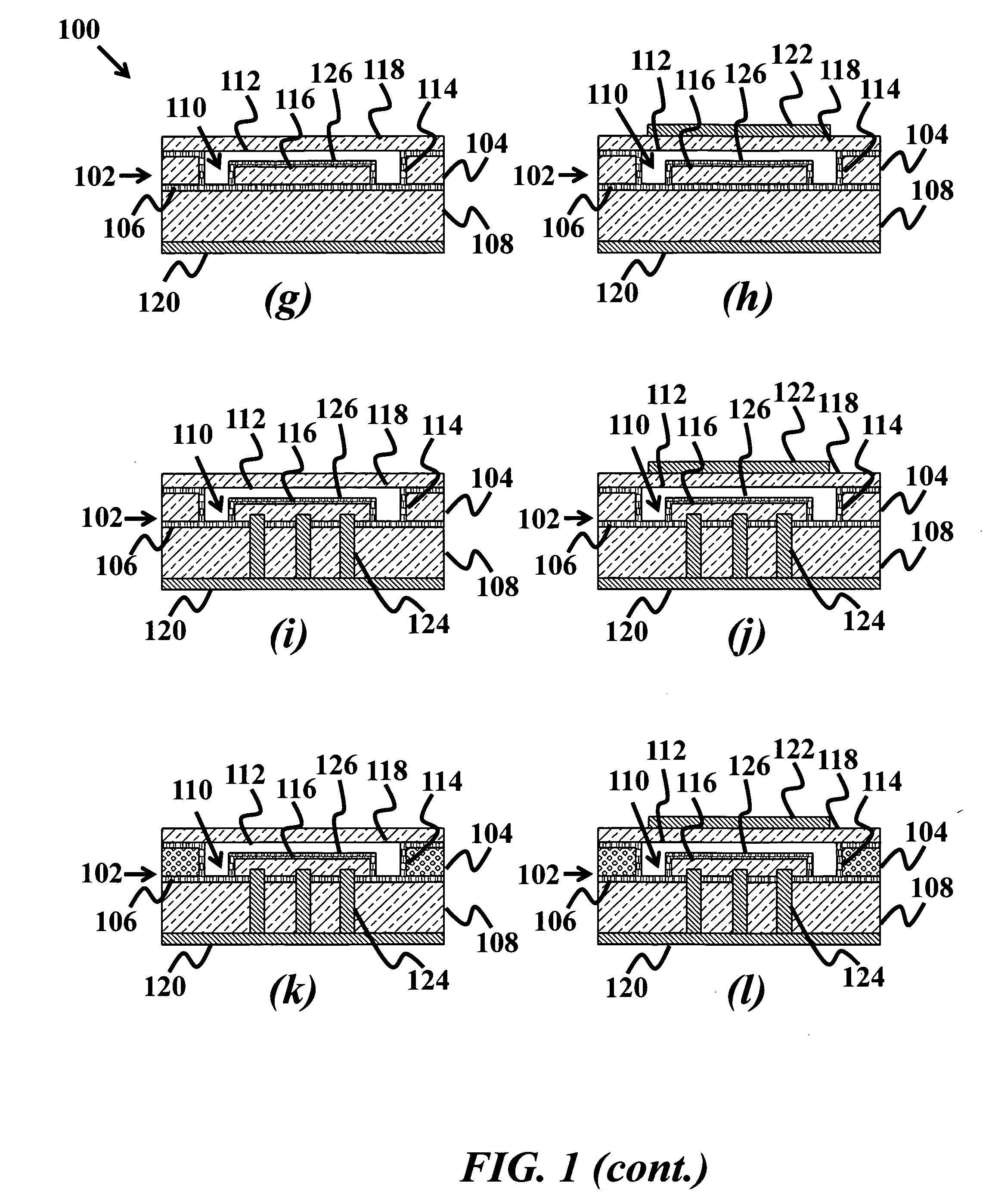
[0054]FIGS. 1(a)-1(r) show different embodiments of the high temperature micromachined ultrasonic transducer (HTCMUT), according to the current invention. FIG. 1(a) shows a HTCMUT having a silicon on insulator (SOI) substrate 102, wherein the SOI substrate 102 includes a doped first silicon layer 104 and a first insulating layer 106, a doped second silicon layer 108, where the first insulating layer 106 is disposed between the first silicon layer 104 and the second silicon layer 108. The HTCMUT 100 further includes a cavity 110 in the fir...


PUM

PropertyMeasurementUnit
thicknessaaaaaaaaaa
hole diameteraaaaaaaaaa
thicknessaaaaaaaaaa

Abstract

A high temperature micromachined ultrasonic transducer (HTCMUT) is provided. The HTCMUT includes a silicon on insulator (SOI) substrate having a doped first silicon layer, a doped second silicon layer, and a first insulating layer disposed between the first and second silicon layers. A cavity is disposed in the first silicon layer, where a cross section of the cavity includes a horizontal cavity portion on top of vertical cavity portions disposed at each end of the horizontal cavity portion, and the vertical cavity portion spans from the first insulating layer through the first silicon layer, such that a portion of the first silicon layer is isolated by the first insulating layer and the cavity. A membrane layer is disposed on the first silicon layer top surface, and spans across the cavity. A bottom electrode is disposed on the bottom of the second silicon layer.

Description

FIELD OF THE INVENTION[0001]The invention relates generally to electrostatic transducers. More particularly, the invention relates to high temperature electrostatic transducers.BACKGROUND[0002]Electrostatic transducers require an insulating structure / layer between their electrodes. In general, this insulating structure / layer has two main functions: it provides electrical isolation so an electrical charge can build up and it gives mechanical support. In state-of-the-art transducers, such as capacitive micromachined ultrasonic transducers (CMUTs), this insulating structure / layer is the main limiting factor in terms of device operation at high temperatures. The likelihood of an electrical breakdown of the insulation structure is dramatically increased at elevated temperatures. Further, parasitic capacitance in the insulation layer will significantly degrade the transducer sensitivity at elevated temperatures due to an increased mobility of trapped charges, for example alkali ions in si...

Claims


Application Information

Patent Timeline
Patent Type & Authority Applications(United States)
IPC IPC(8): H01L29/84H01L21/77B81B7/02
CPCB06B1/0292Y10T29/49005H02N1/008
Inventor KUPNIK, MARIOKHURI-YAKUB, BUTRUS T.
Owner THE BOARD OF TRUSTEES OF THE LELAND STANFORD JUNIOR UNIV
Why Eureka
Try Eureka