Seal system for solid oxide fuel cell and method of making

Inactive Publication Date: 2009-06-04
CORNING INC
View PDF9 Cites 12 Cited by
  • Summary
  • Abstract
  • Description
  • Claims
  • Application Information

AI Technical Summary

Benefits of technology

[0011]The present invention relates to solid oxide fuel cell assembly, and particularly to solid oxide fuel cell assembly that utilize designs and/or seal(s) that can minimi

Problems solved by technology

SOFC devices are typically subjected to thermal-mechanical stresses due to the high operating temperatures and rapid temperature cycling of the device.
Such stresses can result in deformation of device components and can adversely impact the operational reliability and lifetime of SOFC devices.
When a device is comprised of a thin flexible ceramic sheet as the electrolyte component in a SOFC, t

Method used


Image

  • Seal system for solid oxide fuel cell and method of making
  • Seal system for solid oxide fuel cell and method of making
  • Seal system for solid oxide fuel cell and method of making

Examples


Example

Example 1

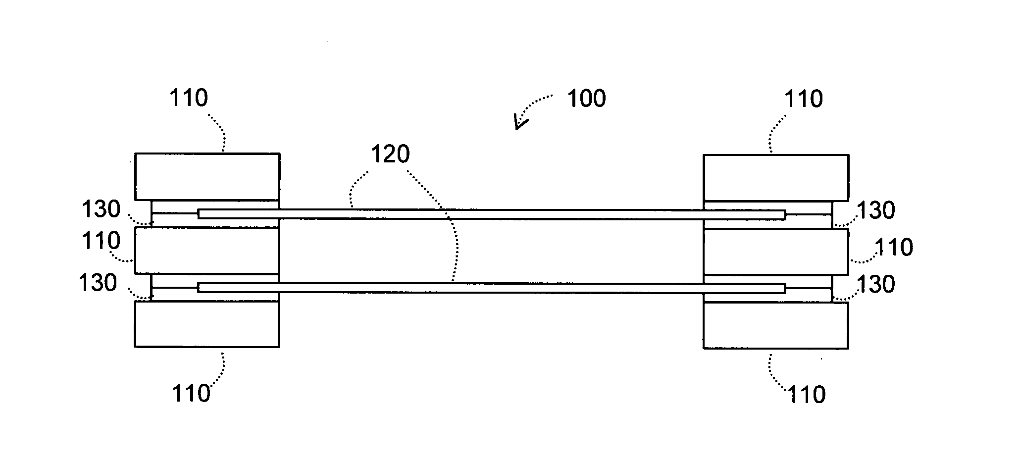
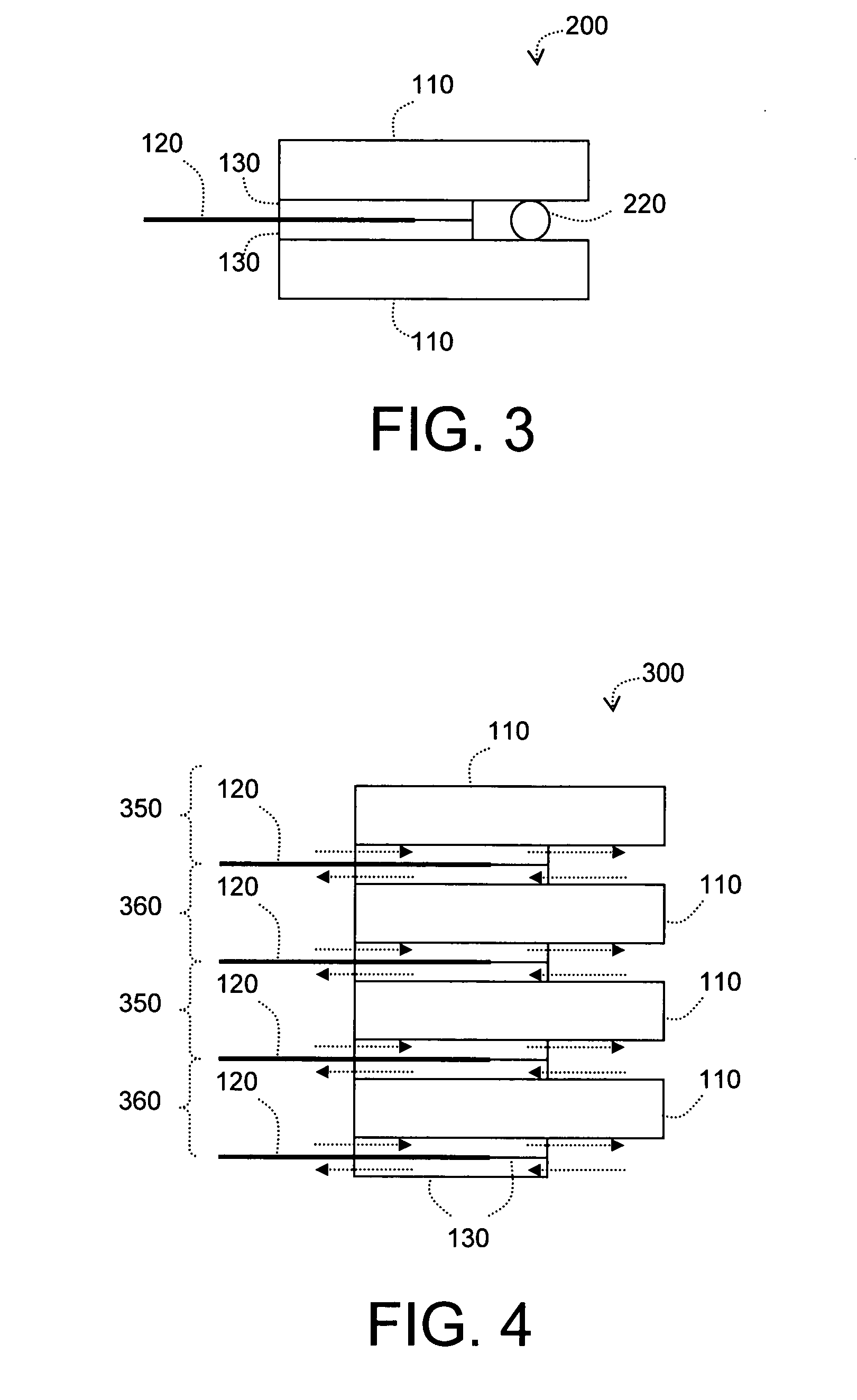
[0087]In a first example, a number of solid oxide fuel cell assemblies, such as that depicted in FIG. 3, were constructed by attaching a zirconia felt seal between stainless steel frame members and a ceramic electrolyte sheet with a stainless steel spacer rod spacer disposed between the frame members and adjacent to the ceramic electrolyte sheet. The assemblies / devices were then tested to determine thermomechanical integrity with various levels of compression between the frame members. When a spacer having a diameter between about 0.115 and about 0.145 inches was used, little to no cracking of the ceramic electrolyte sheet was observed after thermal cycling. The assemblies / devices were tested further by observing the ceramic electrolyte sheet at operating temperature with a 5.0 L / min flow of N2 through the gas manifold of the device. When rod spacers with diameters of about 0.115 to about 0.135 were used at operating temperatures, little to no cracking of the ceramic electr...

Example

Example 2

[0088]In a second example, a plurality of solid oxide fuel assemblies, such as depicted in FIG. 3, were tested to determine the extent of gas leakage. For each device, a zirconia felt seal with an original uncompressed thickness of about 0.1 inches was compressed between a ceramic electrolyte sheet and a first and second frame member. Leakage coefficients were measured at various compression levels of the zirconia felt seal.

[0089]The leakage coefficient of a given felt seal can be defined by the following relationship:

LeakageCoefficient=Leakage(L / min)×Gasketwidth(mm)Pressure(Pa)×Gasketperimeter(mm)

For a plurality of devices, gas leakage can be estimated based on the amount of felt compression and gasket dimensions according to the following relationship:

Leakage(L / min)=Pressure(Pa)×Gasketperimeter(mm)×LeakagecoefficientGasketWidth(mm)

[0090]Using the above cited relationships, gas leakage through assemblies were measured. Generally, a thinner zirconia felt seal resulted in a ...


PUM


Abstract

A solid oxide fuel cell assembly is disclosed comprising a felt seal and a spacer capable of limiting a compressive force applied to the seal system. Also disclosed is a solid oxide fuel cell assembly comprising a seal system comprising a felt seal, wherein at least a portion of the felt seal defines a cavity in contact with a ceramic electrolyte sheet and wherein the cavity comprises at least one of a solid metal wire, a powdered metal, a sintered metal, a powdered ceramic, a sintered ceramic, or a combination thereof. Also disclosed is a solid oxide fuel cell assembly comprising a labyrinth seal that defines a cavity in which at least a portion of a ceramic electrolyte sheet is disposed. Also disclosed is a mounted ceramic electrolyte sheet comprising a ceramic electrolyte sheet and a metal frame positioned adjacent thereto, and a labyrinth seal.

Description

STATEMENT REGARDING GOVERNMENT SUPPORT[0001]This invention was made with government support under Cooperative Agreement 70NANB4H3036, awarded by the National Institute of Standards and Technology (NIST). The United States government has certain rights in this invention.BACKGROUND OF THE INVENTION[0002]1. Field of the Invention[0003]The present invention relates to fuel cell devices and more particularly to solid oxide fuel cell devices that utilize designs and / or seal(s) that can minimize device failure.[0004]2. Technical Background[0005]Solid oxide fuel cells (SOFC) have been the subject of considerable research in recent years. Solid oxide fuel cells (SOFC) are electrochemical cells that convert chemical energy derived from a fuel, such as hydrogen and / or hydrocarbons, into electrical energy via electrochemical oxidation of the fuel at temperatures, for example, of about 700° C. to about 1000° C.[0006]A typical SOFC comprises a negatively-charged oxygen-ion conducting electrolyte ...

Claims


Application Information

Patent Timeline
IPC IPC(8): H01M8/10
CPCH01M8/0273H01M8/0276H01M8/0282Y02E60/525H01M8/124H01M2008/1293Y02E60/521H01M8/1206H01M8/1231Y02E60/50Y02P70/50H01M8/0258
Inventor GREGORSKI, STEVEN JOSEPH
Owner CORNING INC
Why Eureka
Try Eureka