
Microfluidic methods and apparatuses for fluid mixing and valving

Inactive Publication Date: 2009-06-11
SCIEX
View PDF16 Cites 34 Cited by
  • Summary
  • Abstract
  • Description
  • Claims
  • Application Information

AI Technical Summary

Benefits of technology

[0010]According to one embodiment, an apparatus for delivering one or more fluids to a microfluidic channel is provided. The apparatus can include a microfluidic channel in communication with a first conduit for delivering fluids to the microfluidic channel. Further, the apparatus can include a first fluid freeze valve connected to the first conduit and operable to reduce the temperature of the first conduit for freezing fluid in the first conduit such that fluid is prevented from advancing through the first conduit.
[0011]According to a second embodiment, an apparatus for mixing different fluids is provided. The apparatus can include a microfluidic chip comprising a first and second input channel fluidly communicating at a merge location. The microfluidic chip can also include a mixing channel communicating with the first and second input channels at the merge location. The apparatus can also include a first conduit communicating with the merge location for delivering fluids to the merge location. Further, the apparatus can include a first fluid freeze valve connected to the first conduit and operable to reduce the temperature of the first conduit for freezing fluid in the first conduit such that fluid is prevented from advancing through the first conduit.
[0013]According to a fourth embodiment, an apparatus for mixing different fluids is provided. The apparatus can include a microfluidic chip comprising a first and second input channel fluidly communicating at a merge location. The microfluidic chip can also include a mixing channel communicating with the first and second input channels at the merge location. The apparatus can also include an injection loop comprising a first and second end, the first end communicating with the merge location. Further, the apparatus can include a first conduit communicating with the second end of the injection loop for delivering fluids to the injection loop. The apparatus can also include a first fluid freeze valve connected to the first conduit and operable to reduce the temperature of the first conduit for freezing fluid in the first conduit such that fluid is prevented from advancing through the first conduit. Additionally, the apparatus can include a waste unit communicating with the mixing channel via a second conduit. The apparatus can also include a second fluid freeze valve connected to the second conduit and operable to reduce the temperature of the second conduit for freezing fluid in the second conduit such that fluid is prevented from advancing through the second conduit.
[0014]According to a fifth embodiment, a method for delivering one or more fluids to a microfluidic channel is provided. The method can include a step for providing a microfluidic channel. The method can also include a step for providing a first conduit communicating with the microfluidic channel for delivering fluids to the microfluidic channel. Further, the method can include a step for reducing the temperature of the first conduit for freezing fluid in the first conduit such that fluid is prevented from advancing through the first conduit.
[0015]According to a sixth embodiment, a method for mixing different fluids is provided. The method can include a step for providing a microfluidic chip comprising a first and second input channel fluidly communicating at a merge location. The microfluidic chip also comprises a mixing channel communicating with the first and second input channels at the merge location. The method can also include a step for providing a first conduit communicating with the merge location for delivering fluids to the merge location. Further, the method can include a step for reducing the temperature of the first conduit for freezing fluid in the first conduit such that fluid is prevented from advancing through the first conduit.

Problems solved by technology

The number of concentrations measured is limited by the number of dilution steps, which are limited in practice by the time and effort required to make the discrete dilutions, by the time and effort to process the resulting individual reactions, by reagent consumption as the number of reactions increases, and more strictly by pipetting errors that limit the resolution of discrete steps.
Thus far, commercial microfluidic systems have shown some promise in performing point measurements, but have not been employed to mix concentration gradients and particularly continuous gradients due to technologic limitations.
In particular, several challenges remain in the design of industry-acceptable microfluidic systems.
In addition, controlling the signal-to-noise ratio becomes much more challenging when working with nano-scale volumes and flow rates, as certain sources of noise that typically are inconsequential in macroscopic applications now become more noticeable and thus deleterious to the accuracy of data acquisition instruments.
For chemical reactions, such as polymerase chain reaction (PCR), carry-over is not acceptable because this reaction is used to amplify the number of copies of DNA, and contaminating DNA will be faithfully amplified.
The reduction of carry-over can be particularly problematic, especially for microfluidic systems in which flows are extremely small—sometimes as low as a few nanoliters per minute.

Method used


Image

  • Microfluidic methods and apparatuses for fluid mixing and valving
  • Microfluidic methods and apparatuses for fluid mixing and valving
  • Microfluidic methods and apparatuses for fluid mixing and valving

Examples


Embodiment Construction

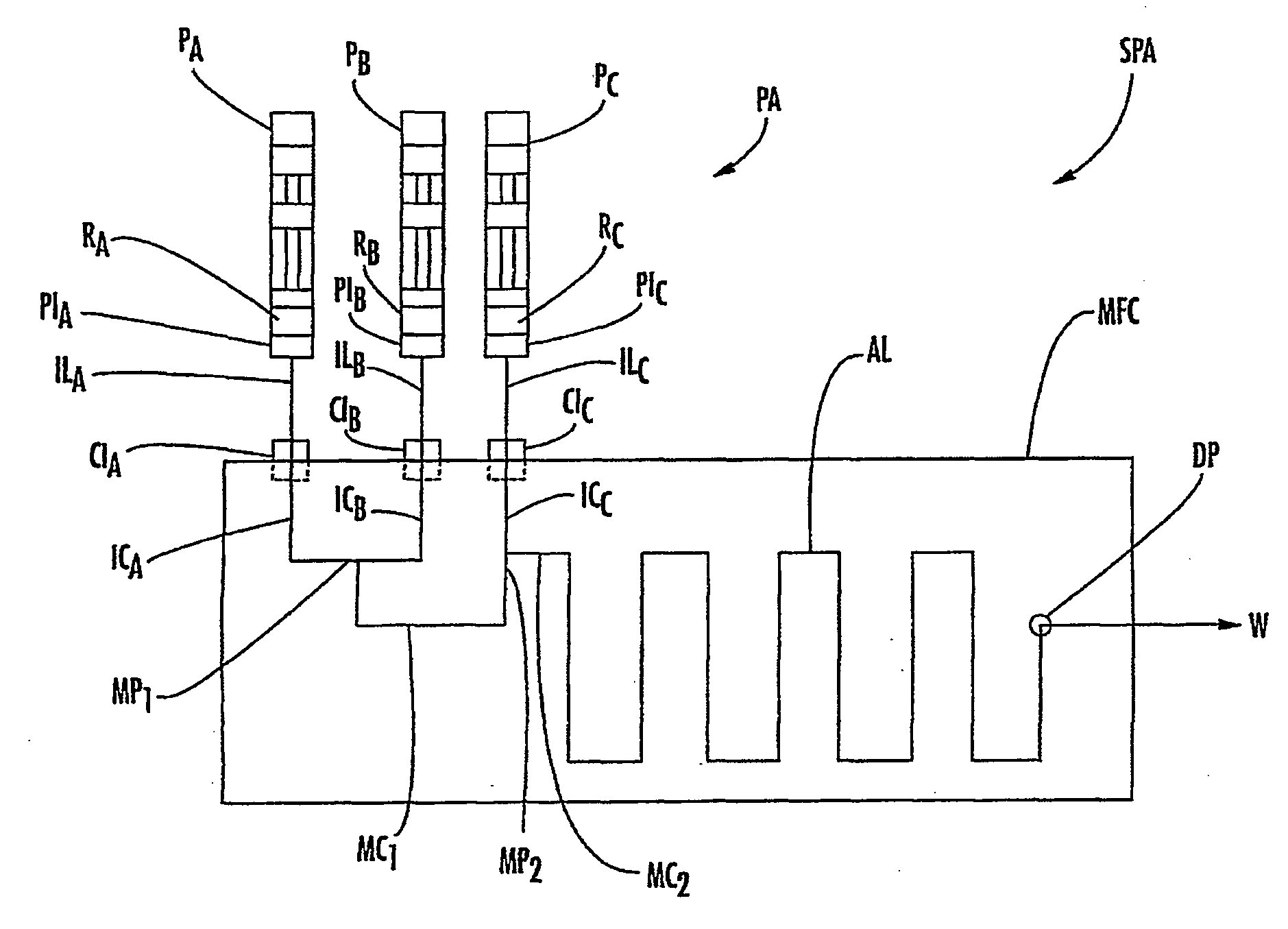
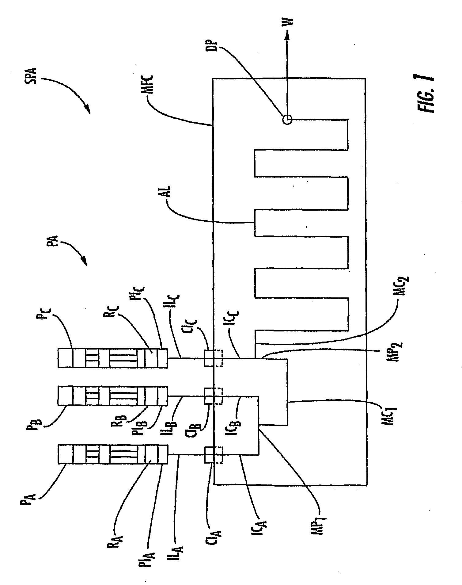
[0069]Microfluidic chips, systems, and related methods are described herein which incorporate improvements for reducing or eliminating noise in the fluid mix concentration. These microfluidic chips, systems, and methods are described with regard to the accompanying drawings. It should be appreciated that the drawings do not constitute limitations on the scope of the disclosed microfluidic chips, systems, and methods.

[0070]As used herein, the term “microfluidic chip,”“microfluidic system,” or “microfluidic device” generally refers to a chip, system, or device which can incorporate a plurality of interconnected channels or chambers, through which materials, and particularly fluid borne materials can be transported to effect one or more preparative or analytical manipulations on those materials. A microfluidic chip is typically a device comprising structural or functional features dimensioned on the order of mm-scale or less, and which is capable of manipulating a fluid at a flow rate ...


PUM


Abstract

According to one embodiment, an apparatus and method for delivering one or more fluids to a microfluidic channel is provided. A microfluidic channel is provided in communication with a first conduit for delivering fluids to the microfluidic channel. Further, the apparatus and method can include a first fluid freeze valve connected to the first conduit and operable to reduce the temperature of the first conduit for freezing fluid in the first conduit such that fluid is prevented from advancing through the first conduit.

Description

CROSS-REFERENCE TO RELATED APPLICATIONS[0001]This application is the U.S. national stage of International Application No. PCT / US06 / 31159, filed Aug. 10, 2006 and entitled MICROFLUIDIC METHODS AND APPARATUSES FOR FLUID MIXING AND VALVING, which claims the benefit of U.S. Patent Application Ser. No. 60 / 707,329, filed Aug. 11, 2005, the disclosure of which is incorporated herein by reference in its entirety. The disclosures of the following U.S. Provisional Applications, commonly owned and simultaneously filed Aug. 11, 2005, are all incorporated by reference in their entirety: U.S. Provisional Application entitled APPARATUS AND METHOD FOR HANDLING FLUIDS AT NANO-SCALE RATES, U.S. Provisional Application No. 60 / 707,421; U.S. Provisional Application entitled MICROFLUIDIC BASED APPARATUS AND METHOD FOR THERMAL REGULATION AND NOISE REDUCTION, U.S. Provisional Application No. 60 / 707,330; U.S. Provisional Application entitled MICROFLUIDIC METHODS AND APPARATUSES FOR FLUID MIXING AND VALVING,...

Claims


Application Information

Patent Timeline
IPC IPC(8): G05D7/06G05D11/13F15C1/02F15C4/00B81B7/00
CPCB01F5/0646G01N35/1097B01F5/0653B01F13/0059B01F15/0404B01L3/502715B01L3/50273B01L3/502738B01L3/565B01L2200/027B01L2300/0816B01L2300/0867B01L2300/1894B01L2400/0487B01L2400/0677F16K99/0001F16K99/0032F16K99/0044F16K2099/0084G01N30/6095B01F5/0647Y10T137/218Y10T137/87652Y10T137/0329Y10T137/2196Y10T137/0391Y10T137/86131Y10T137/0324B01F25/4331B01F25/433B01F25/4336B01F33/30B01F35/81
Inventor SMITH, GREGORY FENTONSCHMIDT, DAWN M.THRALL, SARATEW, DAVID G.VOTAW, GREGORY A.CRENSHAW, HUGH C.POLLACK, MICHAEL G.BEVAN, CHRISTOPHER DAVIDJUNGE, KELLYPATEL, MEHUL
Owner SCIEX
Features
  • Generate Ideas
  • Intellectual Property
  • Life Sciences
  • Materials
  • Tech Scout
  • Unparalleled Data Quality
  • Higher Quality Content
  • 60% Fewer Hallucinations
Learn More