Microfluid based apparatus and method for thermal regulation and noise reduction

a technology of microfluidics and auxiliary devices, applied in lighting and heating apparatus, laboratory glassware, instruments, etc., can solve the problems of inability to mix concentration gradients and particularly continuous gradients, limited number of concentrations measured, and technologic limitations, so as to minimize thermal pumping, reduce noise in the resulting signal, and minimize thermally driven movement

Inactive Publication Date: 2009-06-11
SCIEX
View PDF13 Cites 30 Cited by
  • Summary
  • Abstract
  • Description
  • Claims
  • Application Information

AI Technical Summary

Benefits of technology

[0023]Therefore, it is an object to provide a microfluidic based apparatus and method for thermal regulation to simultaneously (a) control the temperature of a biochemical reaction, (b) minimize thermally-driven movement of the microfluidic chip, (c) minimize thermal pumping driven by differential th

Problems solved by technology

The number of concentrations measured is limited by the number of dilution steps, which are limited in practice by the time and effort required to make the discrete dilutions, by the time and effort to process the resulting individual reactions, by reagent consumption as the number of reactions increases, and more strictly by pipetting errors that limit the resolution of discrete steps.
Thus far, commercial microfluidic systems have shown some promise in performing point measurements, but have not been employed to mix concentration gradients and particularly continuous gradients due to technologic limitations.
In particular, several challenges remain in the design of industry-acceptable microfluidic systems.
In addition, controlling the signal-to-noise ratio becomes much more challenging when working with nano-scale volumes and flow rates, as certain sources of noise that typically are inconsequential in macroscopic applications now become more noticeable and thus deleterious to the accuracy of data acquisition instruments.
However, such pumps suffer from a number of limitations: they generate pulsatile flows, and the flow rates from these pumps depend in a non-linear way upon a number of factors, including the age of the pumps, the frequency with which the pumps are “pulsed”, and their precise location on a chip.
These factors make it difficult to use such pumps to achieve reliable and reproducible flow rates of the sort necessary to achieve controlled gradients.
This fabrication can be extremely costly and time-consuming, and results in a specific pump-architecture that is not flexible or re

Method used


Image

  • Microfluid based apparatus and method for thermal regulation and noise reduction
  • Microfluid based apparatus and method for thermal regulation and noise reduction
  • Microfluid based apparatus and method for thermal regulation and noise reduction

Examples


Embodiment Construction

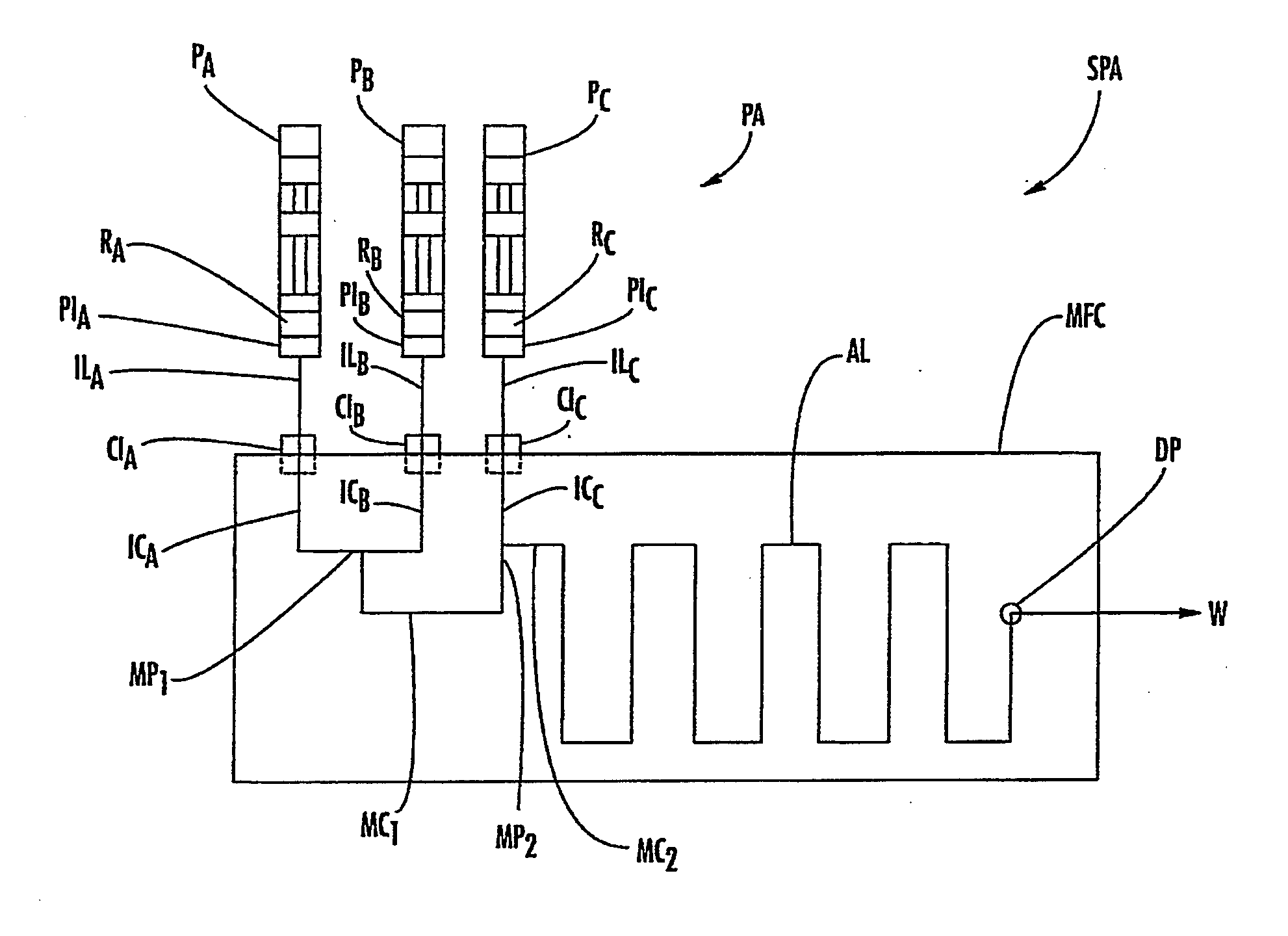
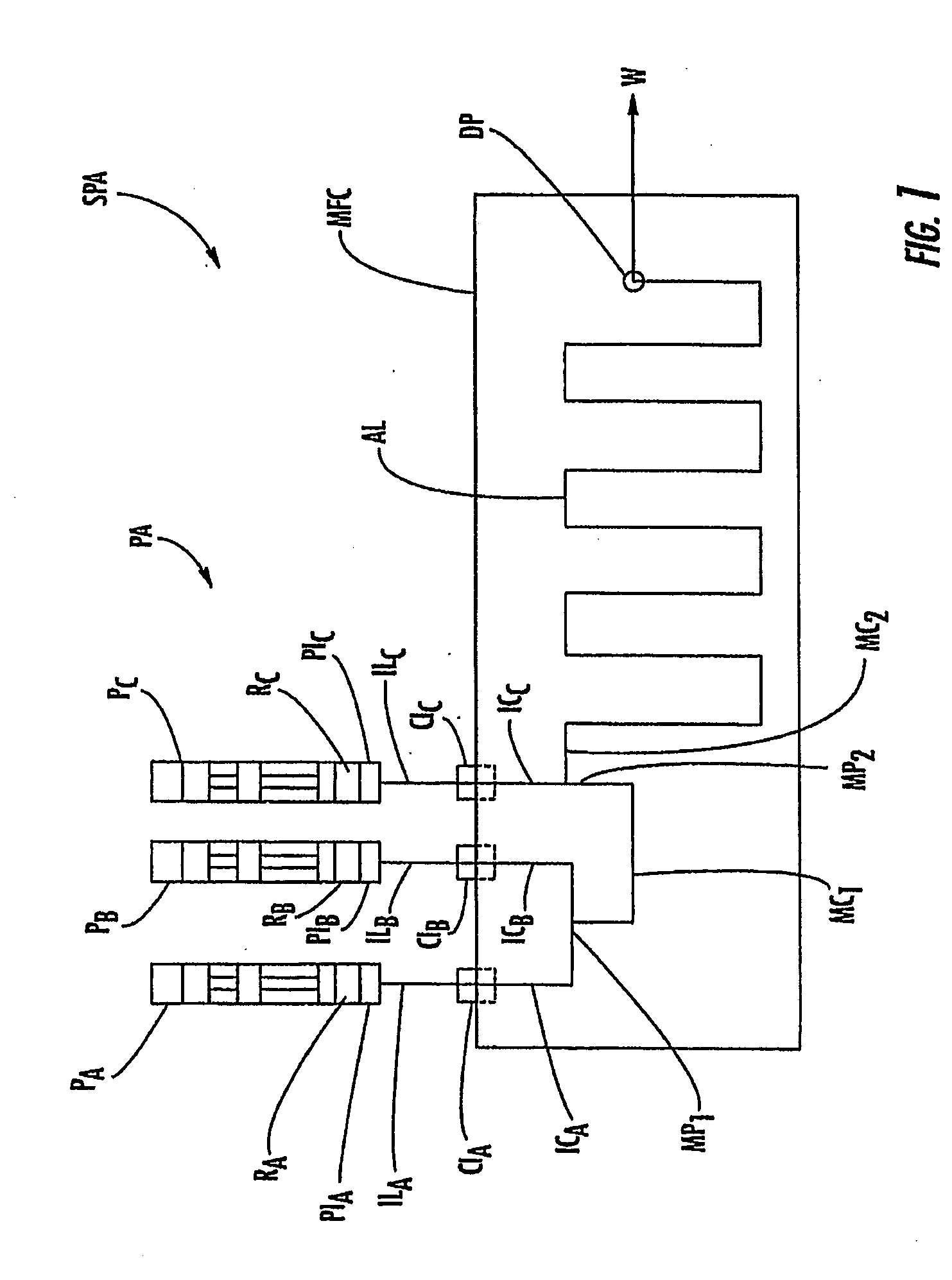
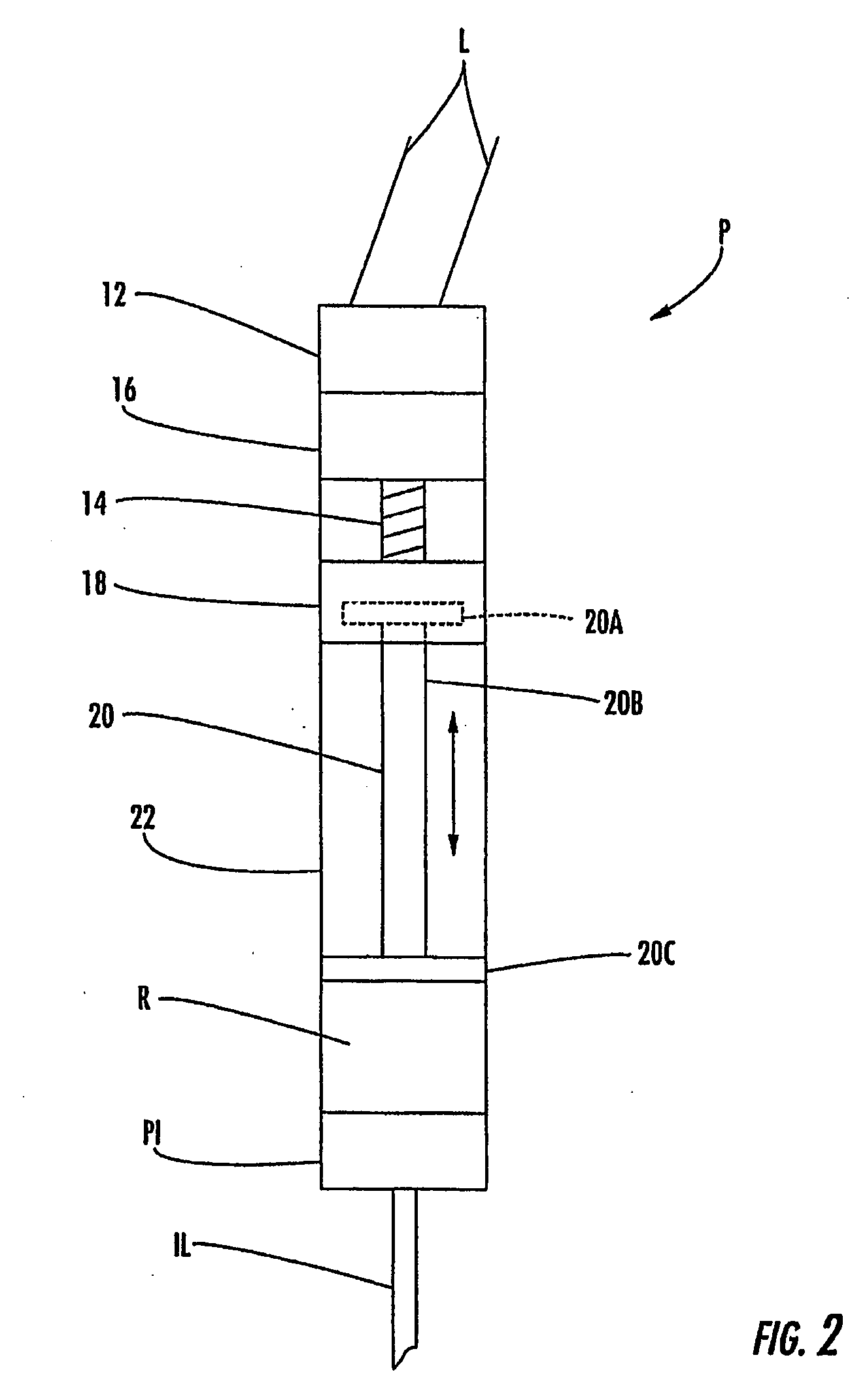
[0047]Microfluidic chips, systems, and related methods are described herein which incorporate improvements for reducing or eliminating noise in the fluid mix concentration. These microfluidic chips, systems, and methods are described with regard to the accompanying drawings. It should be appreciated that the drawings do not constitute limitations on the scope of the disclosed microfluidic chips, systems, and methods.

[0048]As used herein, the term “microfluidic chip,”“microfluidic system,” or “microfluidic device” generally refers to a chip, system, or device which can incorporate a plurality of interconnected channels or chambers, through which materials, and particularly fluid borne materials can be transported to effect one or more preparative or analytical manipulations on those materials. A microfluidic chip is typically a device comprising structural or functional features dimensioned on the order of mm-scale or less, and which is capable of manipulating a fluid at a flow rate ...


PUM


Abstract

An actively temperature regulated microfluidic chip assembly includes a first thermally conductive body, a second thermally conductive body attached to the first thermally conductive body, a microfluidic chip encapsulated between the first and second thermally conductive bodies, and a temperature regulating element mounted to the first thermally conductive body for adding heat to or alternately removing heat from the chip. The temperature of the chip and thus the liquid contained and/or flowing therein can be regulated by measuring the temperature of the liquid and operating the temperature regulating element to establish a thermal gradient toward or alternately away from the liquid based on the measured temperature and in comparison with a desired set point temperature.

Description

CROSS-REFERENCE TO RELATED APPLICATIONS[0001]This application claims the benefit of U.S. Patent Application Ser. No. 60 / 707,330, filed Aug. 11, 2005, the disclosure of which is incorporated herein by reference in its entirety. The disclosures of the following U.S. Provisional Applications, commonly owned and simultaneously filed Aug. 11, 2006, are all incorporated by reference in their entirety: U.S. Provisional Application entitled MICROFLUIDIC APPARATUS AND METHOD FOR SAMPLE PREPARATION AND ANALYSIS, U.S. Provisional Application No. 60 / 707,373 (Attorney Docket No. 447 / 99 / 2 / 1); U.S. Provisional Application entitled APPARATUS AND METHOD FOR HANDLING FLUIDS AT NANO-SCALE RATES, U.S. Provisional Application No. 60 / 707,421 (Attorney Docket No. 447 / 99 / 2 / 2); U.S. Provisional Application entitled MICROFLUIDIC METHODS AND APPARATUSES FOR FLUID MIXING AND VALVING, U.S. Provisional Application No. 60 / 707,329 (Attorney Docket No. 447 / 99 / 2 / 4); U.S. Provisional Application entitled METHODS AND ...

Claims


Application Information

Patent Timeline
IPC IPC(8): F28F27/00B01J19/00
CPCB01J19/0093F28F3/02B01J2219/00822B01J2219/00831B01J2219/00873B01J2219/00891B01J2219/0095B01J2219/00961B01L3/502707B01L3/502715B01L3/50273B01L3/565B01L7/00B01L9/527B01L2200/147B01L2300/1822B01L2300/1827B01L2400/0487B01J2219/00783
Inventor WYRICK, DAVID W.HARTMANN, DANIEL M.NEVILL, JOSHUA T.PATELL, MEHULPOLLACK, MICHAEL G.VOTAW, GREGORY A.CRENSHAW, HUGH C.
Owner SCIEX
Why Eureka
Try Eureka