Water treatment contact filter and water treatment apparatus

a technology of water treatment apparatus and contact filter, which is applied in the direction of biological water/sewage treatment, filtration separation, and separation of processes, etc., can solve the problems of ineffective use of treatment tank capacity, overflow of sewage, and sewage flowing out of treatment tank, so as to improve the surface area of each fibrous material, the effect of improving the capacity of water treatment to be treated and simple structur

Inactive Publication Date: 2009-06-11
ECO WORK
View PDF3 Cites 5 Cited by
  • Summary
  • Abstract
  • Description
  • Claims
  • Application Information

AI Technical Summary

Benefits of technology

[0013]According to a water treatment contact filter according to the first aspect of the invention, since at least a part of a fiber bundle, in which a plurality of fibrous materials are bundled, is fixed to a fixation part, a part, which is not fixed at the fixation part, of these fibrous materials spreads in water to be treated, the surface area of each fibrous material is increased, and thus capacity necessary for treatment of water to be treated can be effectively used. Additionally, since the contact filter is simple in structure, it can be easily manufactured.
[0014]According to a water treatment apparatus of the second aspect of the invention, since the flow of the water to be treated in a treatment tank is horizontally straightened by straightening means, the part, which is not fixed at the fixation part, of the plurality of fibrous materials of the water treatment contact filters according to the first aspect of the invention provided in the treatment tank spreads in the water to be treated, the water to be treated can be efficiently treated by these water treatment contact filters, a great amount of sludge

Problems solved by technology

When the sludge is further deposited on the bottom of the treatment tank, anaerobic filters in the treatment tank are blocked, the sewage can hardly pass through the anaerobic filters, the level of sewage in the treatment tank rises, and this may result in overflow of the sewage.
When the sludge is furthermore deposited on the bottom of the treatment tank, there is a p

Method used


Image

  • Water treatment contact filter and water treatment apparatus
  • Water treatment contact filter and water treatment apparatus
  • Water treatment contact filter and water treatment apparatus

Examples


Embodiment Construction

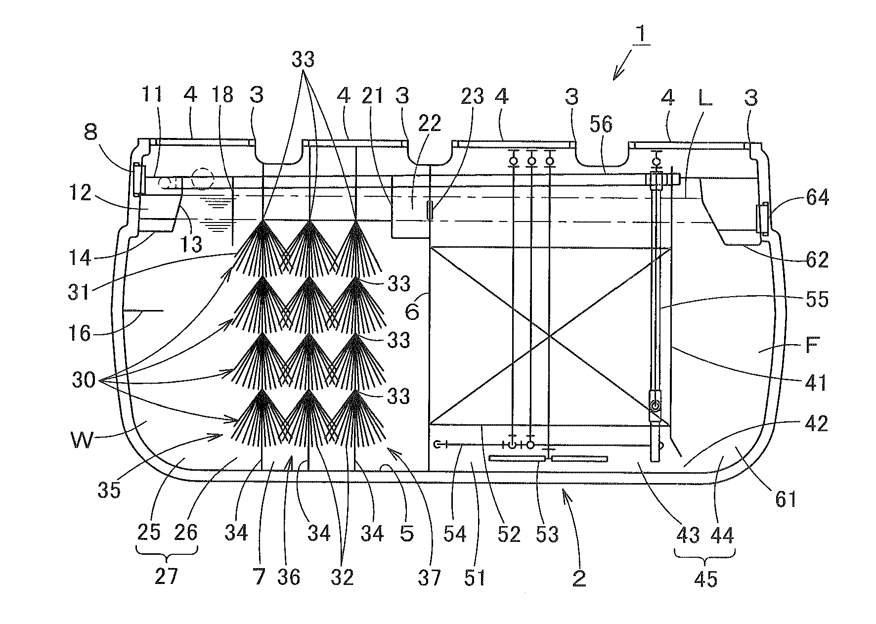
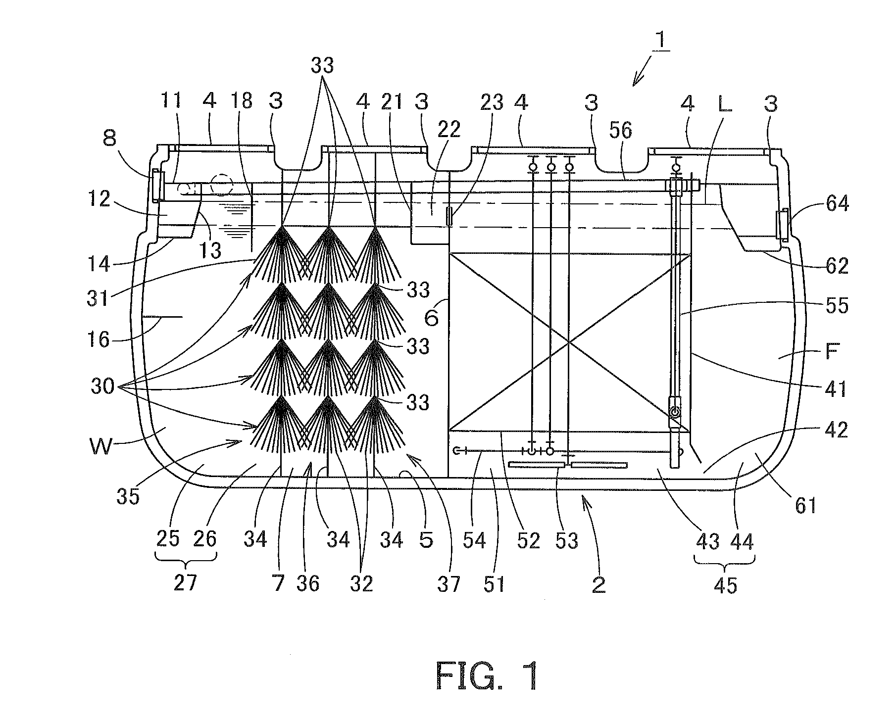
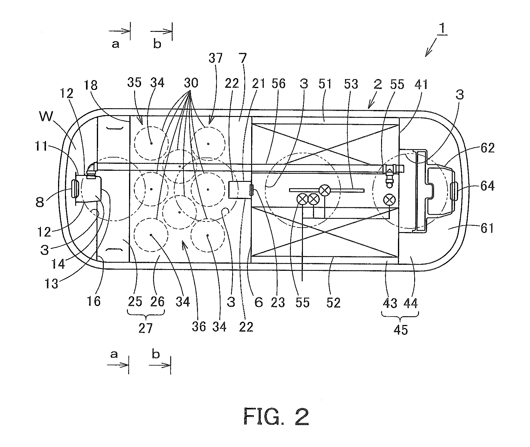
[0021]An embodiment of the water treatment apparatus of the present invention will be described below with reference to FIG. 1 to FIG. 4.

[0022]In FIG. 1 to FIG. 4, the reference numeral 1 denotes a sewage purifier as a water treatment apparatus. The sewage purifier 1 includes a tank body 2 as a treatment tank for storing sewage W as flow-in water to be treated. The tank body 2 is formed in an approximate rectangular shape in a plan view. A plurality of, for example, four openings 3 are arranged at the vertically upper part of the tank body 2 in a longitudinal direction of the tank body 2. A cover 4 is detachably attached to each opening 3. Additionally, a bottom 5 positioned at the vertically lower part of the tank body 2 is formed in an approximate flat shape.

[0023]Further, a first partitioning plate 6 is attached to the middle part of the tank body 2 in the longitudinal direction, and the middle part of the tank body 2 in the longitudinal direction is partitioned by the first part...


PUM

PropertyMeasurementUnit
Flow rateaaaaaaaaaa
Shapeaaaaaaaaaa
Surface areaaaaaaaaaaa

Abstract

This invention provides a fiber filter and a sewage purifier capable of realizing effective use of the capacity of a treatment tank and being easily manufactured. A fiber filter is formed in a manner that ends of a plurality of fibrous materials made of carbon fibers bundled into a fiber bundle are connected to each other at a fixation part. The fiber filter is used as a filter of an anaerobic filter-bed tank of a sewage purifier. A part, which is not fixed at the fixation part, of the fibrous materials of the fiber filter spreads and develops in a tuft shape in sewage. Thus, the surface area of the fiber filter can be increased. Capacity necessary for treatment of the sewage W can be reduced and effectively used. The fiber filter can be easily manufactured due to its simple constitution.

Description

RELATED APPLICATION[0001]The present application claims priority under 35 U.S.C. §119 to Japanese Patent Application No. 2007-314182 filed on Dec. 5, 2007. The content of the application is incorporated herein by reference in its entirety.FIELD OF THE INVENTION[0002]The present invention relates to a water treatment contact filter having a plurality of fibrous materials and a water treatment apparatus provided with the filter.BACKGROUND OF THE INVENTION[0003]Conventionally, this type of water treatment apparatus has an anaerobic filter-bed tank used in a primary treatment part of a sewage purifier. It is known that, in the anaerobic filter-bed tank, the middle part of a treatment tank in a vertical direction is filled with anaerobic filters, and sewage vertically flows through the anaerobic filters (see Patent document 1: Japanese Laid-Open Patent Publication No. 2003-334591).[0004]As described above, in an anaerobic filter-bed tank, foreign matter contained in sewage flowing into t...

Claims


Application Information

Patent Timeline
IPC IPC(8): B01D29/07
CPCC02F3/06C02F3/301C02F3/2806C02F3/103Y02W10/10
Inventor KITAO, TAKANEONUMA, KAZUHIROMATSUMURA, HIROSHI
Owner ECO WORK
Why Eureka
Try Eureka