Methods and apparatus for current sensing

a current sensing and current technology, applied in the direction of ac/dc measuring bridges, process and machine control, instruments, etc., can solve the problems of lossless current sense methods and do not present constant dc impedance to the sense amplifier

Active Publication Date: 2009-06-11
INFINEON TECH AUSTRIA AG
View PDF9 Cites 58 Cited by
  • Summary
  • Abstract
  • Description
  • Claims
  • Application Information

AI Technical Summary

Problems solved by technology

This lossless current sense method, however, does not present a constant DC impedance to the sense amplifier.

Method used


Image

  • Methods and apparatus for current sensing
  • Methods and apparatus for current sensing
  • Methods and apparatus for current sensing

Examples


example 1

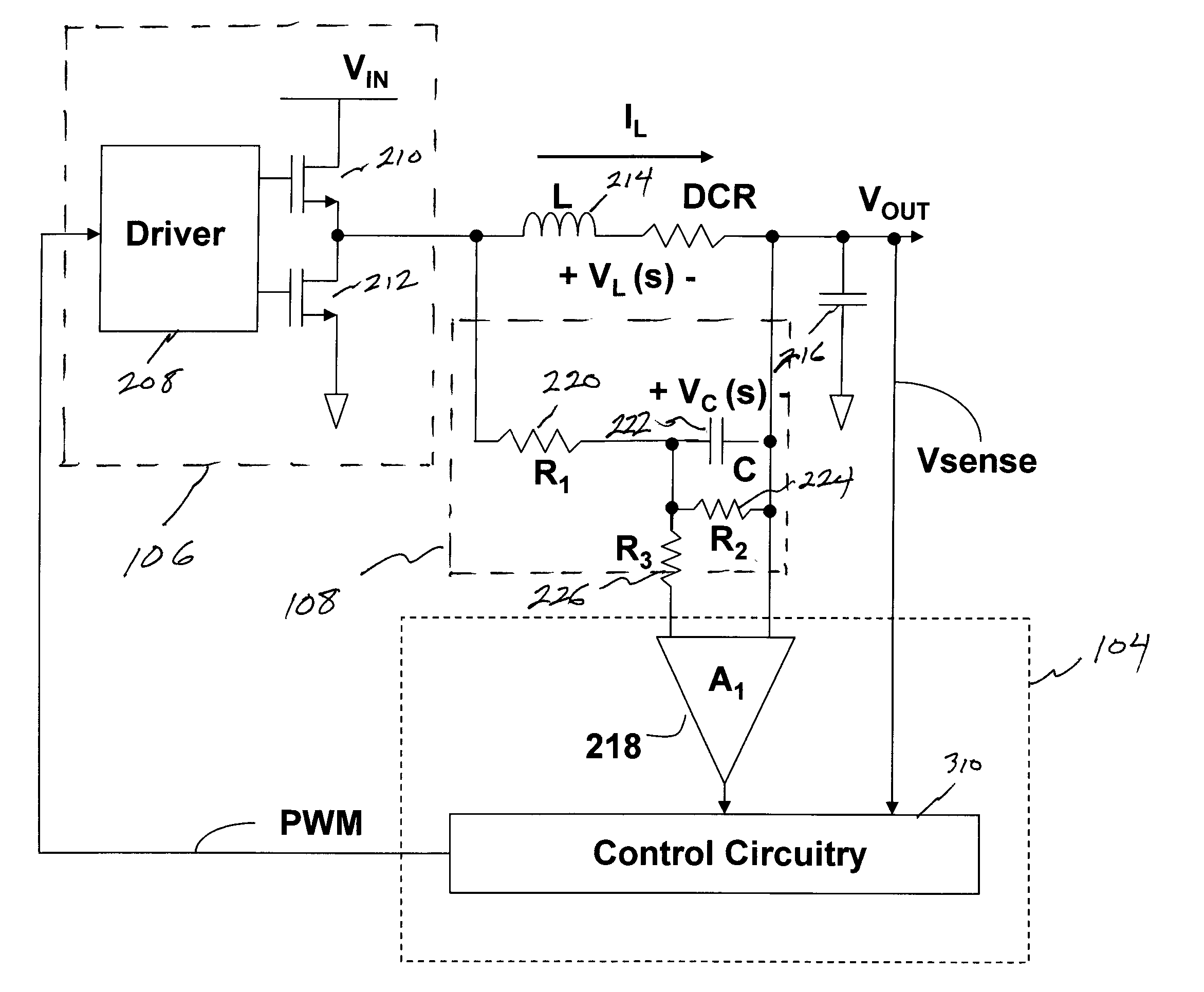
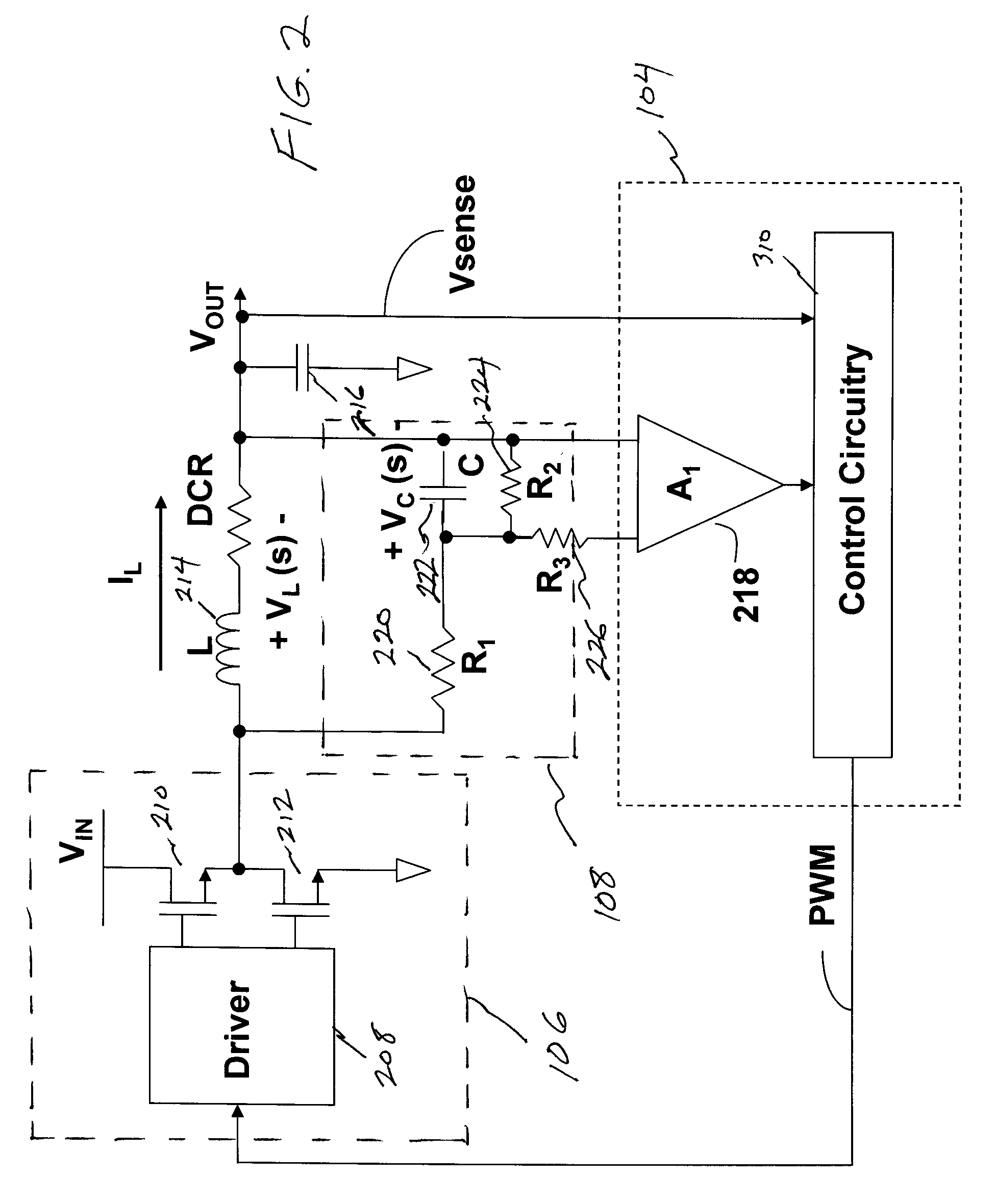
[0034]The values of the various components may be selected according to any appropriate criteria, such as inductor 214 characteristics, capacitor 222 characteristics, desired impedance, and / or maximum sensed voltage. For example, the inductor 214 may have an inductance L of 200 nH with a corresponding DCR of 0.5 mohm. In addition, the inductor 214 may have a maximum current of 20 A and a minimum current of 0 A. A target impedance (K1) of 2 Kohms and a maximum sensed voltage amplitude (K2) of 10 mV may be selected. The capacitor may comprise a standard value choice for C of 0.33 uf.

[0035]Using this data, the values of R1, R2 and R3 to achieve the attributes of constant impedance (2 Kohms) and constant gain (0 to 10 mV) may be selected. For example, the values of R1 and R2 may computed by solving the simultaneous equations:

L / DCR=(R1 / R2)*C

and

IL*DCR*(R2 / (R1+R2)=K2 (maximum sensed voltage amplitude)

[0036]In this case, R1=1.21 Kohms and R2=infinite (or absent from the circuit) would clos...

example 2

[0039]As another example, the inductor 214 may have an inductance value of 600 nH and a DCR of 2 mohm. The inductor 214 may further have a maximum current of 10 A and a minimum of 0 A. The target constant impedance (K1) may again be set at 2 Kohms and the maximum sensed voltage amplitude (K2) at 10 mV. The capacitor may be a standard value choice of C of 0.33 uf.

[0040]The appropriate values of R1, R2 and R3 may be selected to achieve the desired attributes. For example, the values of R1 and R2 are computed by solving the simultaneous equations:

L / DCR=(R1 / R2)*C

and

IL*DCR*(R1 / / R2)=K2

[0041]In this case, values of R1=1.82Kohms and R2=1.82 Kohms closely satisfy the condition.

[0042]Next, the value of R3 may be selected such that (R1 / R2)+R3=K1=2 Kohms. In this case, R3=1.09 Kohms would closely satisfy the condition. Using these values, a target impedance to the amplifier 218 and a desired current sense signal gain are achieved, and may be achieved over a wide range of inductors and DCR val...


PUM


Abstract

Methods and apparatus for current sensing according to various aspects of the present invention sense the current in a circuit, such as an inductor circuit. The current sensing systems may comprise an RC element connected such that the RC time constant matches the L / R time constant of the inductor. The current sensor may be configured to generate voltages that are proportional to the instantaneous current in the inductor with scaled gain for a wide range of inductor self resistance (DCR) values.

Description

CROSS-REFERENCES TO RELATED APPLICATIONS[0001]This application claims the benefit of U.S. Provisional Patent Application No. 61 / 012,894, filed Dec. 11, 2007, and incorporates the disclosure of such application by reference.BACKGROUND OF THE INVENTION[0002]Switching power supplies are popular for high power applications because of the high efficiency and small area / volume required. Buck converters in particular are well suited to providing the high current at low voltages needed by high performance digital integrated circuits such as microprocessors, graphics processors, and network processors. For example, a buck converter is often used to step down a DC voltage (typically referred to as the input voltage) to a lower DC voltage (typically referred to as the output voltage). Since the power stage is fully switched (i.e., the power MOSFET is fully off or on), there is very little loss in the power stage and the converter power efficiency is very high.[0003]Many power supplies operate ...

Claims


Application Information

Patent Timeline
Patent Type & Authority Applications(United States)
IPC IPC(8): G01R19/00
CPCH02M2001/0009H02M3/156H02M1/0009
Inventor OSTROM, KENNETH A.NG, TIMOTHY M.TANG, BENJAMIM
Owner INFINEON TECH AUSTRIA AG
Why Eureka
Try Eureka