Zoom lens, imaging apparatus, and personal data assistant

a technology of zoom lens and imaging apparatus, applied in the field of zoom lens, can solve the problems of too large size, difficult to correct aberration, and imposed more than 38 degrees on the digital camera, and achieve the effect of high variable magnification and high performan

Inactive Publication Date: 2009-06-11
RICOH KK
View PDF53 Cites 54 Cited by
  • Summary
  • Abstract
  • Description
  • Claims
  • Application Information

AI Technical Summary

Benefits of technology

[0018]An object of the present invention is to provide a zoom lens, an imaging apparatus, a personal data assistant in which various aberrations such as chromatic aberration of magnification, chromatic coma aberration, or the like can be appropriately corrected while

Problems solved by technology

But in contrast to such a large variable magnification ratio, the half angle of view at the wide-angle end is about 33 degrees in JPH8-248318A and about 34 degrees in JP2005-215165A so that the requirement of more than 38 degrees imposed on a digital camera is not satisfied.
However, in this case, an aperture and the third optical system (third lens group) have an integrated constitution so that when the angle of view is widened, the optical systems disposed after the aperture towards the object side become too large and it becomes difficult to correct the aberration.
However, in this case, an aperture and the third optical system (third

Method used


Image

  • Zoom lens, imaging apparatus, and personal data assistant
  • Zoom lens, imaging apparatus, and personal data assistant
  • Zoom lens, imaging apparatus, and personal data assistant

Examples


first embodiment

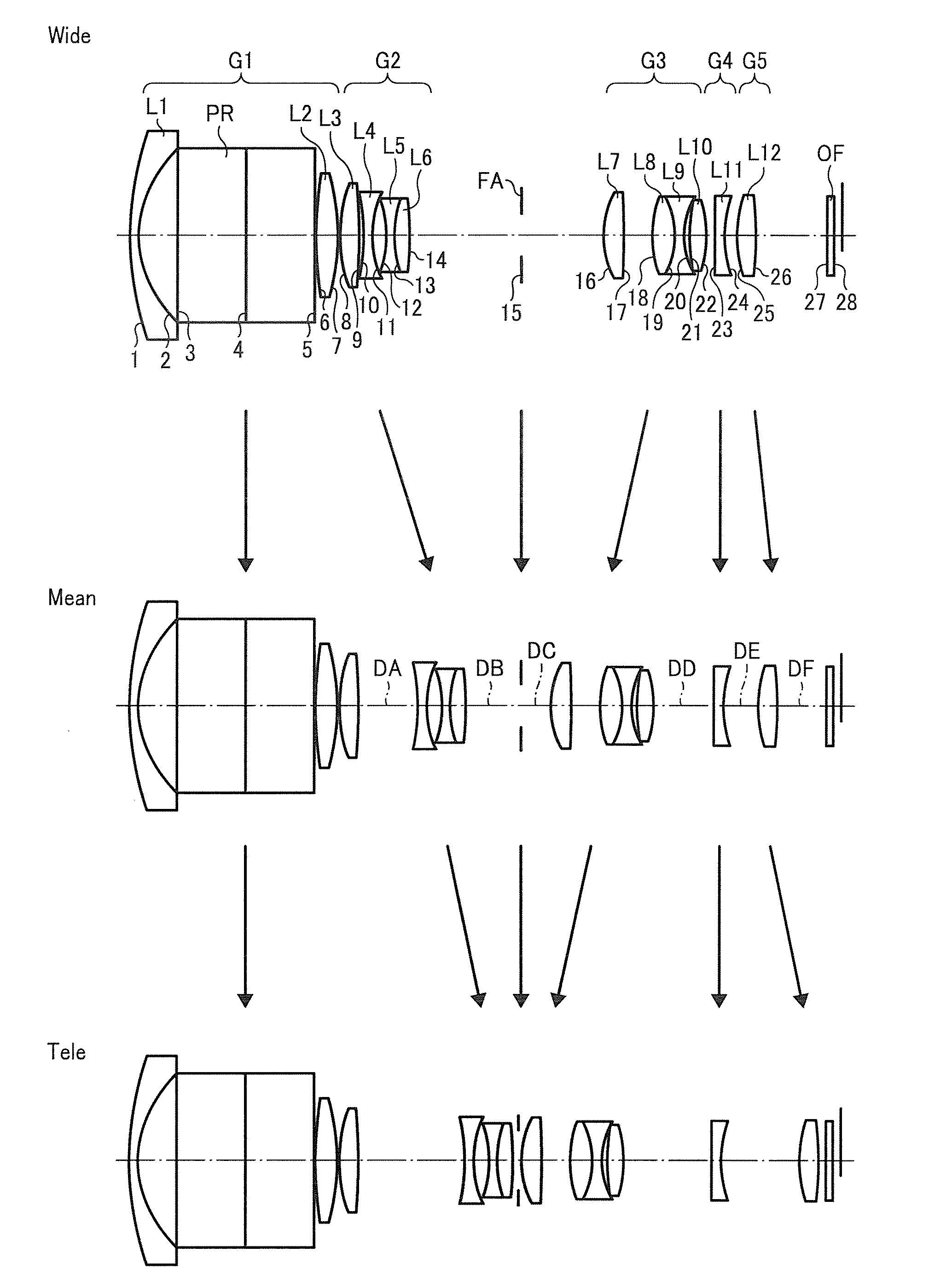
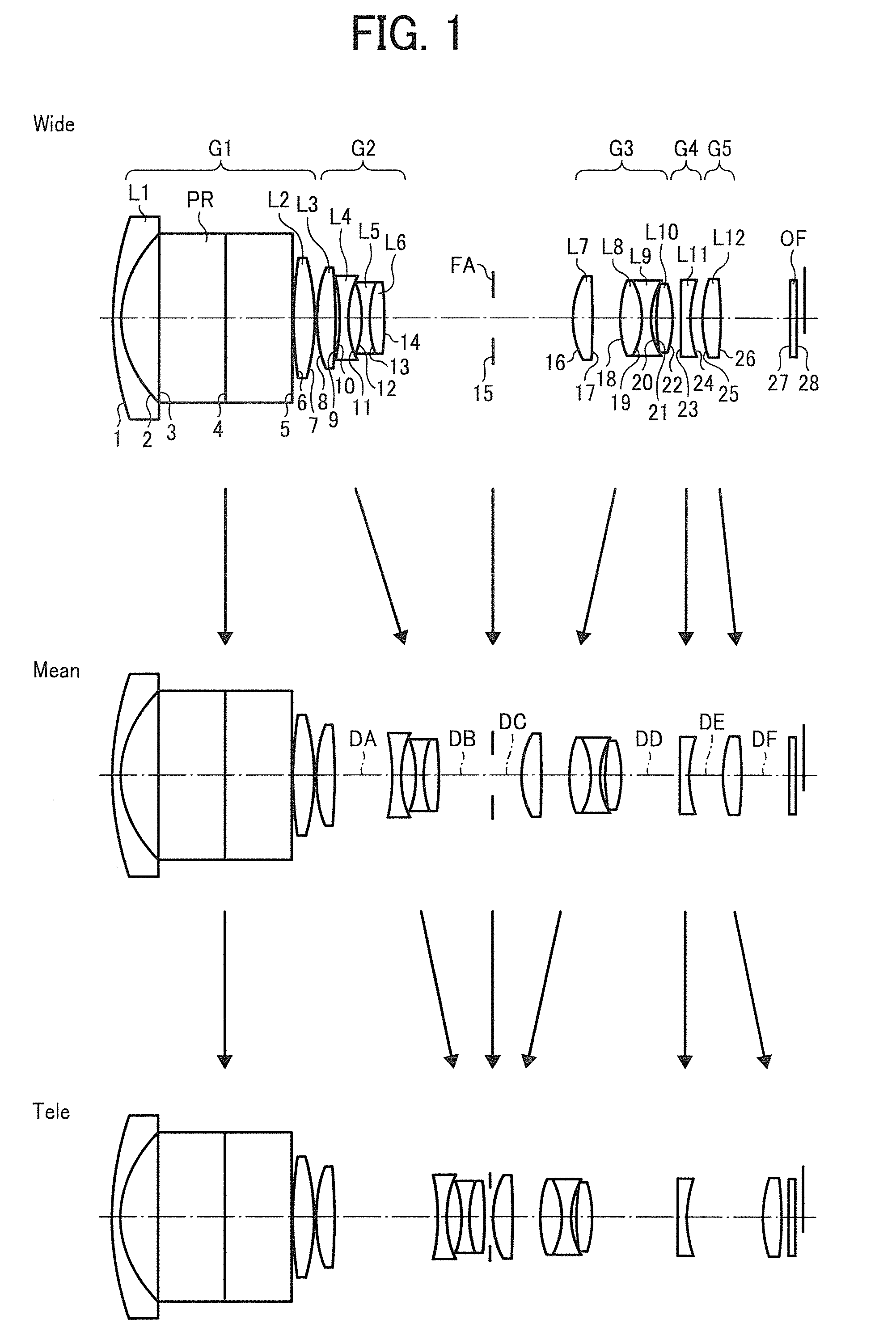
[0068]A zoom lens according to a first embodiment of the present invention includes a first optical system or a first lens group G1 having a positive focal length, a second optical system or a second lens group G2 having a negative focal length) a third optical system or a third lens group G3 having a positive focal length, a fourth optical system or a fourth lens group G4 having a negative focal length, and a fifth optical system or a fifth lens group G5 having a positive focal length, which are arranged in order from an object side. The zoom lens has also an aperture stop provided at an object side of the third optical system and the first optical system may include a deflection optical element.

[0069]When changing a magnification of the zoom lens from a short focus end to a long focus end, an interval between the first optical system and the second optical system increases, an interval between the second optical system and the aperture stop decreases, an interval between the apert...

example 1

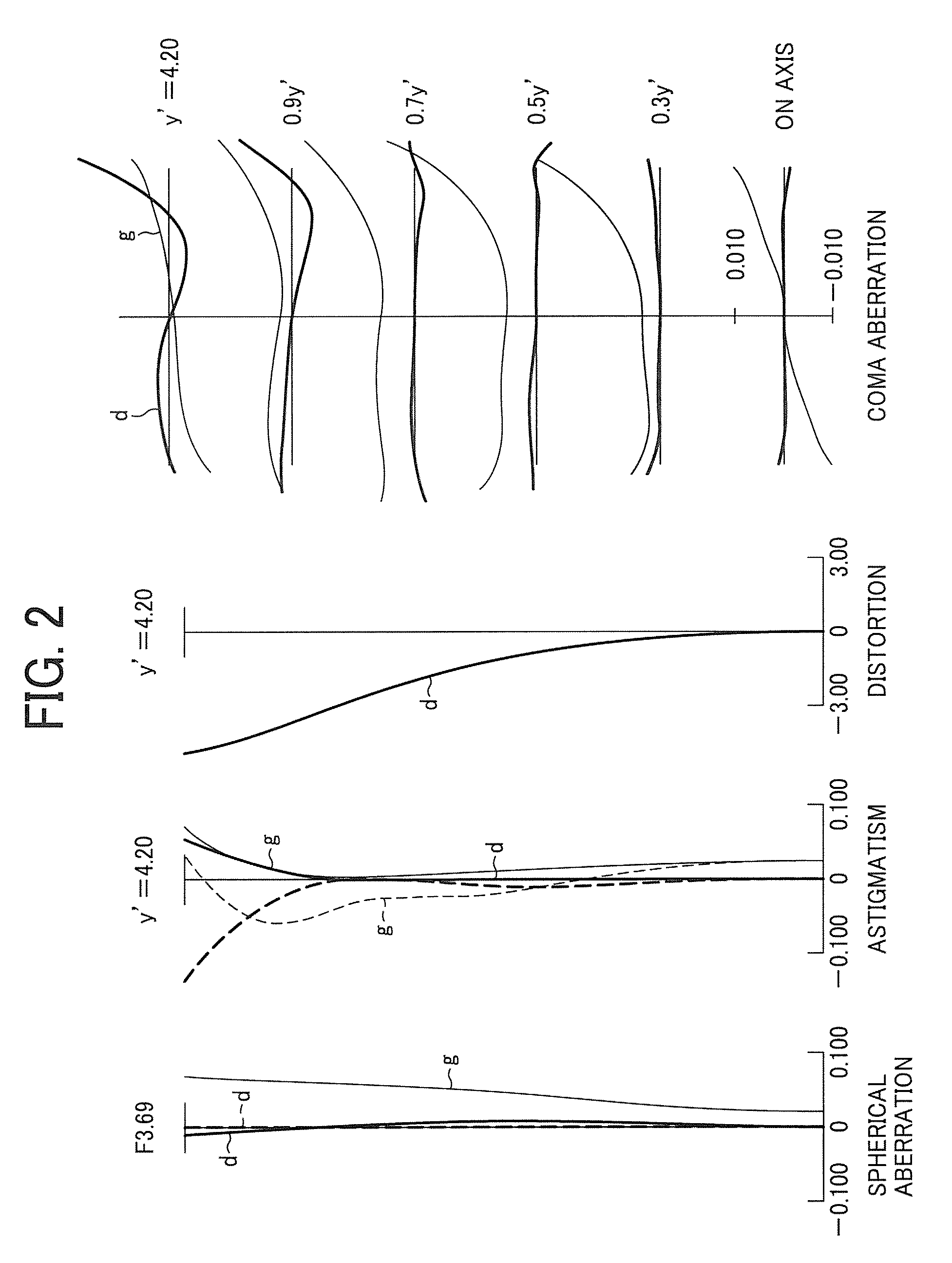
[0089]Specific examples of the zoom lens according to the first embodiment of the present invention will be explained in detail. Examples 1, 2, 3, and 4 show specific configurations of the zoom lens according to this embodiment based on the specific examples. In Examples 1 to 4, the configurations and the specific examples are shown.

[0090]In Examples 1 to 4, the zoom lens further includes an optical element, which is disposed at an image side of the fifth lens group and is formed in a parallel plate form. The optical element is, for example, an optical filter such as an optical low-pass filter, an infrared cut filter or the like, or a cover glass (seal glass) of a light-receiving element such as a COD sensor or the like and is referred to as a filter hereinafter.

[0091]In addition, in Examples 1 to 4, aspheric surfaces in an image-side surface of a lens disposed at the most object side of the first lens group G1, an image-side surface of a lens disposed at most object side of the sec...

example 2

[0167]FIG. 5 shows a configuration of optical systems of the zoom lens according to Example 2 of the present invention. The positions of each of the lens groups in changing from a short focus end (WIDE) to a long focus end (TELE) through an intermediate focal length position (MEAN) are shown in FIG. 5. Movement loci of each of the lens groups in zooming are also schematically shown in FIG. 5.

[0168]The zoom lens shown in FIG. 5 includes a first lens L1, a second lens L2, a third lens L3, a fourth lens L4, a fifth lens L5, a sixth lens L6, a seventh lens L7, an eighth lens L8, a ninth lens L9, a 10th lens L10, an 11th lens L11, a 12th lens L12, a prism PR, an aperture stop FA and the filter OF. In this case, the first lens L1, the prism PR, the second lens L2, and the third lens L3 constitute the first optical system G1, the fourth to sixth lenses L4 to LB constitute the second optical system G2, the seventh to 10th lenses L7 to L10 constitute the third optical system G3, the 11th len...


PUM


Abstract

A zoom lens includes a first optical system having a positive focal length, the first optical system, a second optical system having a negative focal length, a third optical system having a positive focal length, a fourth optical system having a negative focal length, and a fifth optical system having a positive focal length, which are arranged in order from an object side to an image side and an aperture stop provided at an object side of the third optical system. The following condition is satisfied:
0.5<(T23w/Y′)/(ft/fw)<1.0
where T23w is an interval between the second optical system and the third optical system at the short focus end, Y′ is a maximum image height of the zoom lens, ft is a focal length of the zoom lens at the long focus end, and fw is a focal length of the zoom lens at the short focus end.

Description

CROSS REFERENCE TO RELATED APPLICATIONS[0001]The present application is based on and claims priority from Japanese Application Numbers 2007-317756 filed on Dec. 7, 2007 and 2008-079377 filed on Mar. 25, 2008, the disclosures of which are hereby incorporated by reference herein in their entirety.BACKGROUND OF THE INVENTION[0002]1. Field of the Invention[0003]The present invention relates to a zoom lens which selects and sets a focal length as needed within a predetermined focal length range. The present invention further relates to an improved zoom lens having a large aperture, a wide angle of view in addition to a small size, high image quality and a high variable magnification ratio. The zoom lens according to the present invention can also be used in a silver salt camera with a silver salt film but the zoom lens is preferably used in an imaging apparatus using an electronic image pickup device which converts images into digital information. In particular, the present invention rel...

Claims


Application Information

Patent Timeline
IPC IPC(8): G02B15/16
CPCG02B15/173G02B15/1461G02B15/145121
Inventor SUDOH, YOSHIFUMIATSUUMI, HIROMICHI
Owner RICOH KK
Why Eureka
Try Eureka