Light Guide Member, Planar Lighting Device Using the Same, and Rod-Type Lighting Device

Active Publication Date: 2009-06-11
FUJIFILM CORP
View PDF12 Cites 23 Cited by
  • Summary
  • Abstract
  • Description
  • Claims
  • Application Information

AI Technical Summary

Benefits of technology

[0053]The light guide member according to the first aspect of the present invention is capable of admitting light inside through the second light guide unit and emitting light through the light emitting plane of the first light guide member, permitting use of a point light source such as a light emitting diode (LED) in place of a cold cathode tube and, hence, a thinner design.
[0054]Because, furthermore, the external shape of the second light guide unit can be machined to match the shape of a parallel groove of the first light guide unit, the generation of unevenness in brightness can be reduced and a thin light guide member can be obtained by forming the parallel groove of the first light guide unit into a shape that will limit unevenness in brightness while machining the external shape of the second light guide unit into a matching shape. To be brief, the shape of the parallel groove of the first light guide unit and the external shape of the second light guide unit can be freely designed in order to limit bright lines occurring on the light emitting plane of the first light guide unit. Further, since the second light guide unit contains light-scattering particles of a given property, sufficient light can be emitted through the light emitting plane without depending on a complicated structure, thus enhancing the light use efficiency. Thus, a rod-type light source with such simplified structure makes low-cost manufacturing possible. The light guide member thus configured is optimum for use in backlight units of liquid crystal display panels.
[0055]Further, the planar lighting device according to the second aspect of the present invention, using point light sources as illumination light sources such as light emitting diodes having an adjustable light source wavelength instead of cold cathode tubes, is capable of high color reproducibility and, hence, allows expansion of the col

Problems solved by technology

However, the backlight unit of direct illumination type mentioned above presented a limit to how thin the thickness could be made beca

Method used


Image

  • Light Guide Member, Planar Lighting Device Using the Same, and Rod-Type Lighting Device
  • Light Guide Member, Planar Lighting Device Using the Same, and Rod-Type Lighting Device
  • Light Guide Member, Planar Lighting Device Using the Same, and Rod-Type Lighting Device

Examples


first embodiment

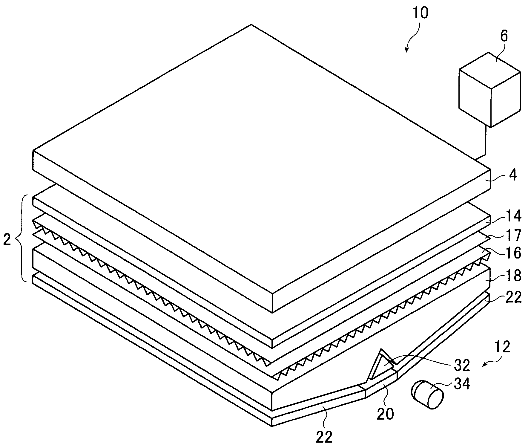
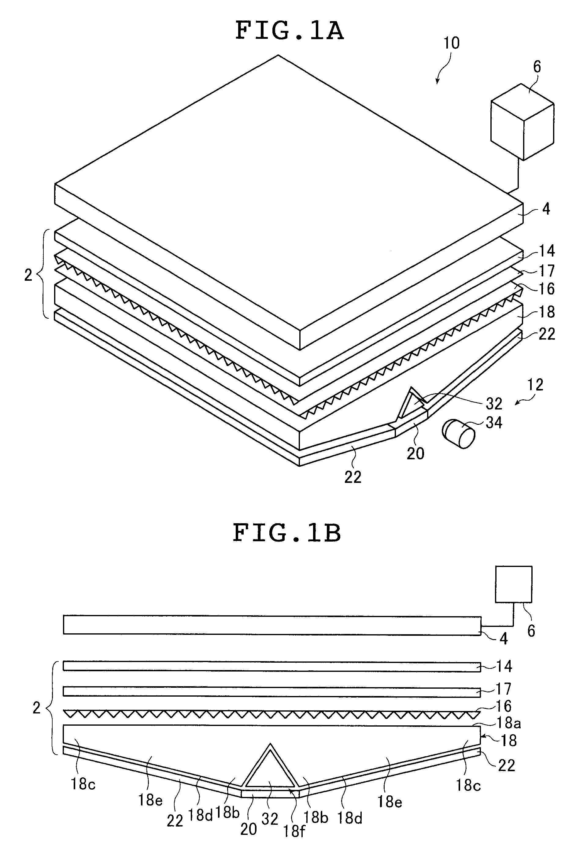
[0129]FIG. 1A is a schematic perspective view of a liquid crystal display device using the inventive planar lighting device (also referred to as “backlight unit” below).

[0130]A liquid crystal display device 10 basically comprises a planar lighting device 2, a liquid crystal display panel 4 disposed on the light emission side of the planar light device 2, and a drive unit 6 for driving them.

[0131]The liquid crystal display panel 4 displays characters, figures, images, etc., on the liquid crystal display panel by using the changes in refractive index caused in the liquid crystal cells as electric field is partially applied to liquid crystal molecules arranged beforehand in a given direction to change the orientation of the molecules.

[0132]The planar lighting device 2 is a device to irradiate the entire surface of the liquid crystal display panel 4 with a uniform light from behind the liquid crystal display panel 4 and has a light emitting plane with substantially same dimensions as an...

second embodiment

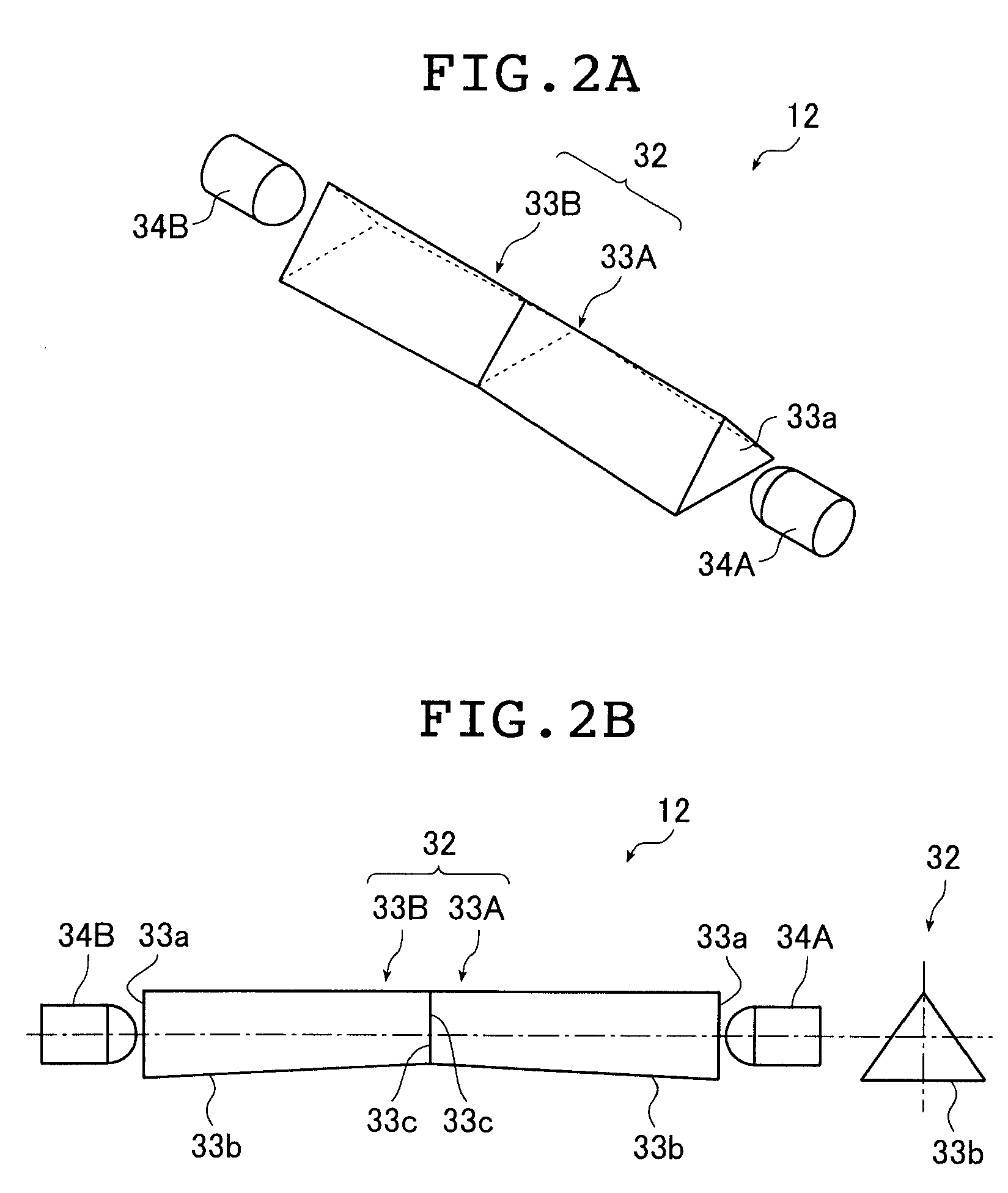
[0300]In the second embodiment, the LEDs 34A and 34B are placed each in one location (not shown) and light emitted from the LEDs 34A and 34B is led to the end surfaces of the light guide units 32 through optical fibers as illustrated in FIG. 25.

[0301]A planar lighting device of a type that admits light via optical fibers and through both end surfaces of the rod-type light guide units will be described referring to FIGS. 25 to 30, whereas a planar lighting device of a type that admits light via optical fibers and through one of the end surfaces of the rod-type light guide units will be described referring to FIGS. 31 to 34.

[0302]FIG. 25 schematically illustrates how light from the LEDs is led via optical fibers to the juxtaposed light guide plates. FIG. 26A is a schematic cross-sectional view of the light guide plate 18 forming a planar lighting device having light guide units disposed on the wall surfaces defining the parallel groove of the light guide plate; FIG. 26B is a schematic...

third embodiment

[0328]Now, a third embodiment of the present invention will be described referring to FIGS. 35 to 39. The third embodiment of the planar lighting device is configured by connecting light guide plates each having a wedge-like sectional shape such that end surfaces of the light guide plates are in close contact with each other. The planar lighting device having such a configuration will be referred to as a tandem-type planar lighting device below.

[0329]FIG. 35 is a schematic perspective view of a liquid crystal display device in which juxtaposed light guide plates are used in a tandem-type planar lighting device.

[0330]FIG. 36 illustrates an example of a tandem-type planar lighting device that admits light through both end surfaces of light guide units. FIGS. 36A, 36B and 36C are, respectively, a schematic cross-sectional view of light guide plates of a tandem-type planar lighting device comprising the inventive rod-type lighting devices, a partial, enlarged cross-sectional view thereo...


PUM


Abstract

A transparent light guide member comprising a first light guide unit in the form of a transparent plate having a rectangular light emitting plane and a parallel groove formed on a rear surface located opposite from the rectangular light emitting plane and parallel to one side of the rectangular light emitting plane; and a second light guide unit, which is transparent, having a columnar external shape to be accommodated in the parallel groove and containing light-scattering particles. Let Φ be the scattering cross section of the particles, LG the length of the light guide unit 32 in the direction in which light propagates, Np the particle density, and KC a compensation coefficient, then a value Φ·LG·Np·KC the light guide member assumes is not smaller than 1.1 and not greater than 8.2, and the compensation coefficient KC is not smaller than 0.005 and not greater than 0.1.

Description

TECHNICAL FIELD[0001]The present invention relates to a light guide member used in a lighting device such as a backlight unit, a planar lighting device using the same, and a rod-type lighting device.BACKGROUND ART[0002]A liquid crystal display device uses a backlight unit to illuminate its liquid crystal panel (LCD) by radiating light from the rear side of the liquid crystal panel.[0003]The backlight unit is configured using such parts as a light source for illumination, a light guide plate for dispersing light emitted from the light source to irradiate the liquid crystal display panel therewith, and a prism sheet and a diffusion sheet for rendering the light radiated from the light guide plate uniform.[0004]Currently, large liquid crystal televisions predominantly use a backlight unit of a type called a direct illumination type (see JP 05-4133 U, for example). A backlight unit of that type has cold cathode tubes provided as light sources on the rear side of the liquid crystal displ...

Claims


Application Information

Patent Timeline
IPC IPC(8): F21V8/00G02B6/00
CPCG02B6/0021G02B6/0028G02B6/0031G02B6/0068G02B6/0046G02B6/005G02B6/0055G02B6/0041
Inventor IWASAKI, OSAMU
Owner FUJIFILM CORP
Why Eureka
Try Eureka