Lithium cell

a primary cell and lithium technology, applied in the field of primary cells, can solve the problems of less efficient discharge of cathode active materials than anode active materials, “severing” of electrical contact, and risk of discontinuities on the lithium anode surface as the cell continues, and achieve good affinity and cohesive properties

Active Publication Date: 2009-06-11
DURACELL U S OPERATIONS
View PDF13 Cites 39 Cited by
  • Summary
  • Abstract
  • Description
  • Claims
  • Application Information

AI Technical Summary

Benefits of technology

[0022]The invention is directed to lithium primary cells wherein the anode comprises lithium metal. The lithium may be alloyed with small amounts of other metal, for example aluminum, which typically comprises less than about 1 or 2 wt. % of the lithium alloy. The lithium which forms the anode active material, is preferably in the form of a thin foil. The cell has a cathode comprising the cathode active material iron disulfide (FeS2), commonly known as “pyrite”. The cell may be in the form of a button (coin) cell or flat cell. Desirably the cell may be in the form of a spirally wound cell comprising an anode sheet and a cathode composite sheet spirally wound with separator therebetween. The cathode sheet is produced using a slurry process to coat a cathode mixture comprising iron disulfide (FeS2) and carbon particles onto a substrate, preferably a conductive metal substrate. The FeS2 and carbon particles are bound to the substrate using desirably an elastomeric, preferably, a styrene-ethylene / butylene-styrene (SEBS) block copolymer such as Kraton G1651 elastomer (Kraton Polymers, Houston, Tex.). This polymer is a film-former, and possesses good affinity and cohesive properties for the FeS2 particles as well as for conductive carbon particle additives in the cathode mixture. The polymer resists chemical attack by the electrolyte.

Problems solved by technology

One reason for this is that the cathode active material discharges less efficiently than the anode active material.
However, in a Li / FeS2 cell, if the cell is balanced in this manner with cathode in excess as in U.S. Pat. Nos. 6,849,360 B2 and 7,157,185 B2 there is risk of creating discontinuities in the lithium anode surface as the cell continues to discharge.
That is, as cell discharge proceeds, the lithium anode layer becomes thinner and thinner and eventually can lead to “severing” of the electrical contact between anode and anode current collector, which electrically connects the anode material to the negative terminal.
This of course can result in delay or permanent disruption of cell performance before the expected cutoff voltage is reached.
One of the difficulties associated with the manufacture of a Li / FeS2 cell is the need to add good binding material to the cathode formulation to bind the Li / FeS2 and carbon particles together in the cathode.
This is because undesirable oxidation / reduction reactions between the electrolyte and electrode materials (either discharged or undischarged) could thereby gradually contaminate the electrolyte and reduce its effectiveness or result in excessive gassing.
This in turn can result in a catastrophic cell failure.
Thus, it should be evident from the above representative references that the choice of a particular organic solvent or mixture of different organic solvents for use in conjunction with any one or more lithium salts to produce a suitable electrolyte for the Li / FeS2 cell is challenging.
But rather the challenge associated with such cells using an electrolyte formed with just any combination of known lithium salt and organic solvent is that the problems encountered will likely be very substantial, thus making the cell impractical for commercial usage.
Thus, references which merely provide long lists of possible organic solvents for Li / FeS2 cells do not necessarily teach combinations of solvents or combination of specific lithium salts in specific solvent mixtures, which exhibit particular or unexpected benefit.

Method used


Image

  • Lithium cell
  • Lithium cell
  • Lithium cell

Examples


example

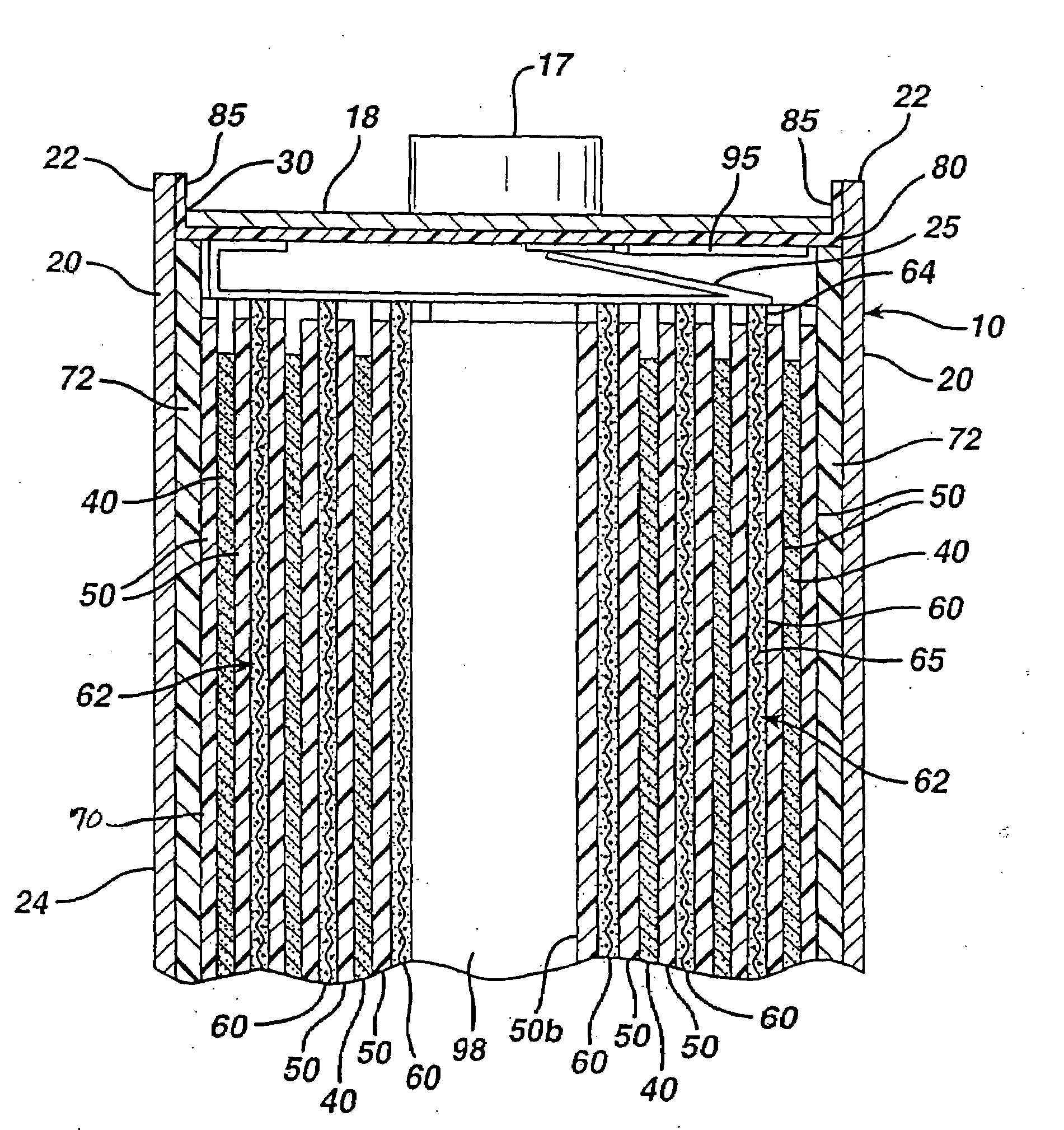
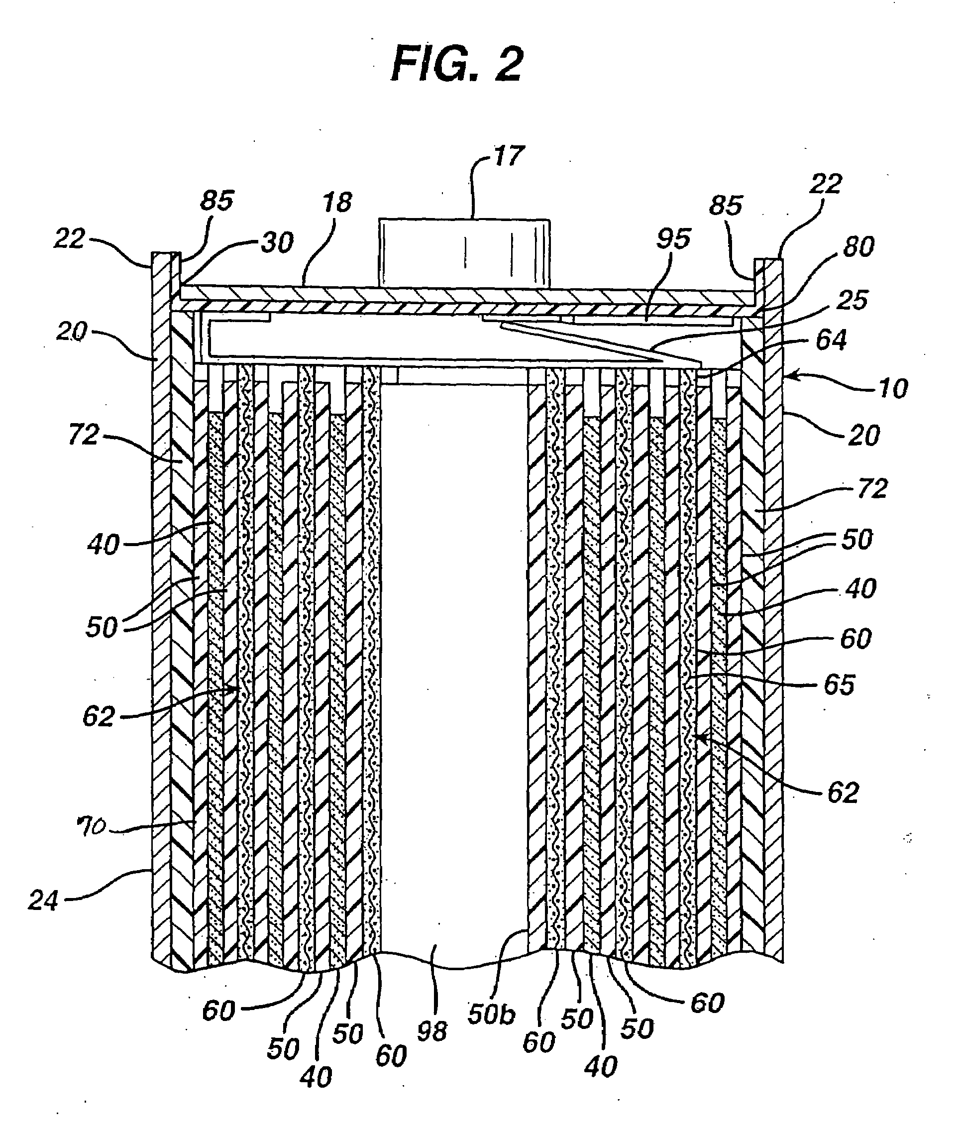
[0066]Test AA size cylindrical cells were made in accordance with the preceding description and are representative of a specific embodiment of the invention. The test AA cells were all identical and made according to the following specifications.

[0067]The cathode was coated in the form of a wet cathode slurry as earlier described herein onto both sides of an aluminum foil substrate 65. The aluminum foil had a thickness of about 15 micron. The wet cathode slurry was coated first on one side of foil substrate 65 and then dried as described herein. The wet cathode slurry was then coated onto the opposite side of substrate 65 and then dried. The dried cathode coatings 60 were then calendered to compress the coating thickness, thus forming a dry coating 60 on both sides of substrate 65 resulting in cathode composite 62. The cathode composite 62 had a total thickness of about 0.124 mm, which includes the thickness of substrate 65 (15 micron) and dry cathode coating 60 on both sides of sub...


PUM

PropertyMeasurementUnit
interfacial surface areaaaaaaaaaaa

Abstract

A primary electrochemical cell having an anode comprising lithium and a cathode comprising iron disulfide (FeS2) and carbon particles. The cell is balanced so that the anode is in theoretical capacity excess (mAmp-hrs) compared to the theoretical capacity of the cathode. The anode and cathode can be spirally wound with separator therebetween and inserted into the cell casing with electrolyte then added. The electrolyte comprises a lithium salt dissolved in organic solvent.

Description

FIELD OF THE INVENTION[0001]The invention relates to lithium primary cells having an anode comprising lithium and a cathode comprising iron disulfide, wherein the ratio of the theoretical capacity of the anode to theoretical capacity of the cathode is greater than 1.0.BACKGROUND[0002]Primary (non-rechargeable) electrochemical cells having an anode of lithium are known and are in widespread commercial use. The anode is comprised essentially of lithium metal. Such cells typically have a cathode comprising manganese dioxide, and electrolyte comprising a lithium salt such as lithium trifluoromethane sulfonate (LiCF3SO3) dissolved in a nonaqueous solvent. The cells are referenced in the art as primary lithium cells and are generally not intended to be rechargeable. A common primary lithium cell has a lithium anode and cathode comprising MnO2 (Li / MnO2 cell) used to power 35 mm cameras. Alternative primary lithium cells with lithium metal anodes but having different cathodes, are also know...

Claims


Application Information

Patent Timeline
Patent Type & Authority Applications(United States)
IPC IPC(8): H01M2/02H01M2/30H01M4/06H01M4/58H01M50/417H01M50/491
CPCH01M2/022H01M4/58H01M4/0435H01M4/12H01M4/382H01M4/581H01M4/5815H01M6/10H01M6/166H01M6/168H01M6/50H01M2004/021H01M2006/5094H01M2300/0037Y02E60/12H01M2/1653H01M4/06H01M4/40H01M6/16H01M50/107H01M50/417H01M50/491Y02E60/10
Inventor SPECHT, STEVEN J.POZIN, MICHAELKOUZNETSOVA, YELENAPATEL, BHUPENDRA K.BERKOWITZ, FRED J.
Owner DURACELL U S OPERATIONS
Why Eureka
Try Eureka