Engine exhaust emission purification apparatus

a technology of exhaust emission and purification apparatus, which is applied in the direction of machines/engines, exhaust treatment electric control, separation processes, etc., can solve the problems of clogging of injection holes of injection nozzles, becoming impossible to obtain the required performance of exhaust emission purification, and becoming impossible to make an injection supply of liquid reducing agent from injection nozzles

Active Publication Date: 2009-06-18
VOLVO TRUCK CORP
View PDF43 Cites 4 Cited by
  • Summary
  • Abstract
  • Description
  • Claims
  • Application Information

AI Technical Summary

Benefits of technology

[0010]Therefore, taking into account the above problems of the conventional apparatus, it is an object of the present invention to provide an exhaust emission purification apparatus in which clogging of an injection hole of an injection nozzle may be prevented by maintaining a temperature of at least a part of a liquid reducing agent supply system provided with an injection nozzle and piping for the nozzle at a temperature lower than a boiling point of a solvent or equal to or higher than a melting point of dissolved matter.
[0015]With the exhaust emission purification apparatus according to the invention, at least a part of the liquid reducing agent supply system provided with the injection nozzle and the associated piping for the injection nozzle is maintained by the temperature maintenance device at a temperature either lower than the boiling point of the solvent of the liquid reducing agent or equal to or higher than the melting point of the dissolved matter. Therefore, the liquid reducing agent existing in the liquid reducing agent supply system implements heat exchange with the liquid reducing agent supply system to thereby be maintained at a temperature lower than the boiling point of the solvent or at a temperature equal to or higher than the melting point of the dissolved matter. Therefore, a phenomenon in which only the solvent evaporates in the liquid reducing agent supply system and the dissolved matter is precipitated does not occur. If the dissolved matter is precipitated, the dissolved matter melts away. As a result, clogging of an injection hole of the injection nozzle may be prevented. Because injection / supply failure of the liquid reducing agent is avoided, a required amount of liquid reducing agent according to an operating state of the engine can be injection-supplied to obtain necessary exhaust emission purification performance.

Problems solved by technology

However, with the conventional exhaust emission purification apparatus, the injection hole of the injection nozzle might be clogged during the supply of the liquid reducing agent by injection and the injection for supplying the liquid reducing agent will become impossible in some cases.
As a result, the reduction reaction of NOx in the reduction catalytic converter would not proceed to result in emission of the NOx before it is purified and therefore, it might become impossible to obtain a required performance for the exhaust emission purification.
It is assumed that this problem is caused by such a phenomenon that only a solvent evaporates and the dissolved matter of the liquid reducing agent is precipitated in the injection nozzle when a temperature of the injection nozzle increases under an influence of exhaust heat and a temperature of the liquid reducing agent increases to or over a boiling point of the solvent.
In this case, the dissolved matter remains precipitated in the injection nozzle and the piping for the nozzle, and therefore it becomes impossible to make an injection supply of the liquid reducing agent from the injection nozzle.
As a result, exhaust emission purification by the reduction catalytic converter may become insufficient to resultantly cause emission of a large amount of NOx.
Such a problem becomes prominent especially when the injection supply of the liquid reducing agent stop under a condition where the temperatures of the injection nozzle and the piping for the nozzle equal to or higher than the boiling point of the solvent or when an amount of liquid reducing agent supplied by injection is small.

Method used


Image

  • Engine exhaust emission purification apparatus
  • Engine exhaust emission purification apparatus
  • Engine exhaust emission purification apparatus

Examples


first embodiment

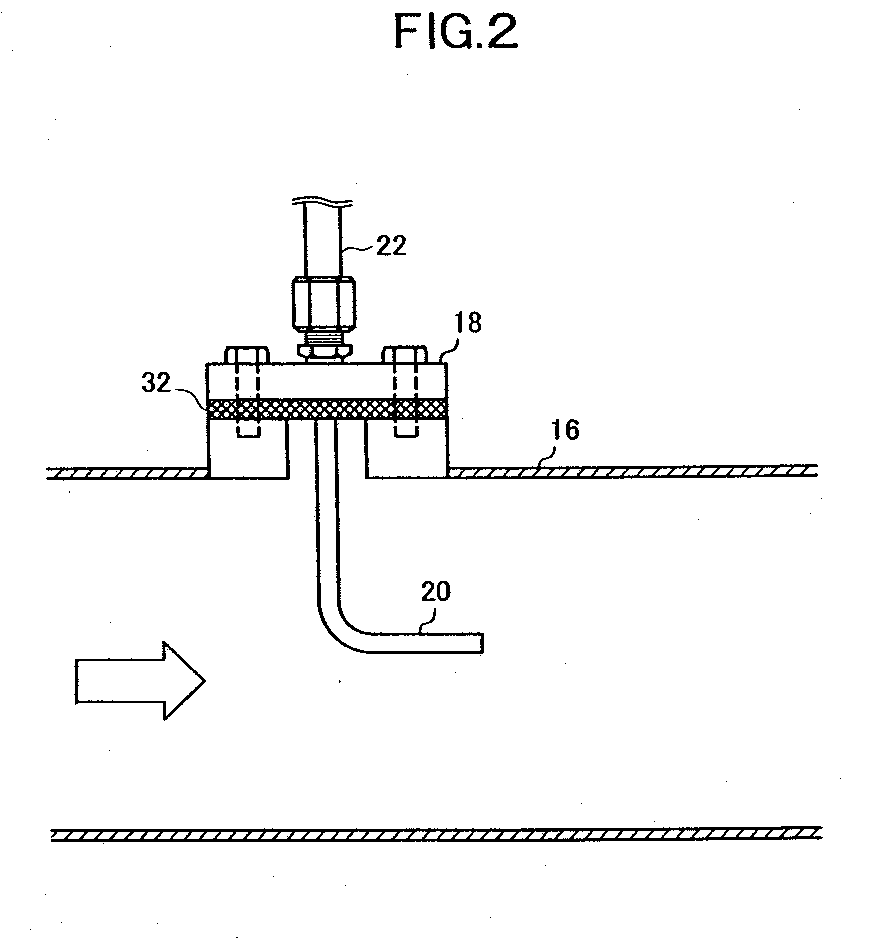
[0034]FIG. 2 shows the temperature maintenance device.

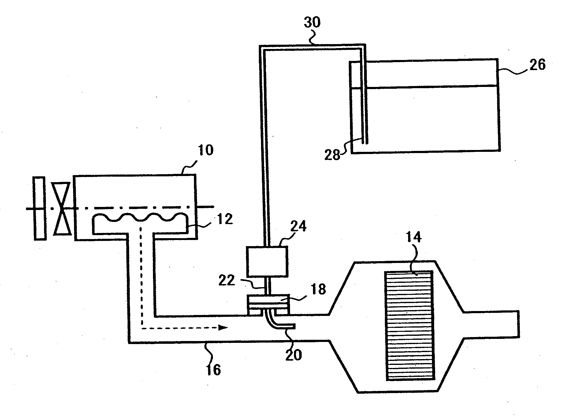
[0035]The temperature maintenance device is formed of a heat insulating member, e.g., a gasket 32 made of material with low thermal conductivity disposed between the exhaust pipe 16 and the flange 18. With this structure, heat of the exhaust emission from the engine 10 is insulated by the gasket 32 and therefore becomes less likely to be transferred to the flange 18. Then, increase in a temperature of the flange 18 is suppressed and the temperature is maintained at a temperature lower than the boiling point of water. As a result, the temperatures of the injection nozzle 20 and the piping 22 connected to the flange 18 become lower than the boiling point of water. Therefore, a phenomenon in which only moisture evaporates from the urea aqueous solution and urea is precipitated becomes less likely to occur to thereby avoid injection / supply failure of the urea aqueous solution caused by clogging of the injection hole of the injection ...

second embodiment

[0036]FIG. 3 shows the temperature maintenance device.

[0037]The temperature maintenance device is formed of a plurality of radiating fins 34 provided to be juxtaposed to an outer surface of the flange 18. With this structure, even when the exhaust heat of the engine 10 is transferred to the flange 18, the heat is radiated from the radiating fins 34 into the air to thereby suppress an increase in the temperature of the flange 18 and maintain the temperature at a temperature value lower than the boiling point of water. As a result, the temperatures of the injection nozzle 20 and the piping 22 connected to the flange 18 become lower than the boiling point of water to thereby exert similar advantageous effects to those exhibited by the preceding first embodiment.

third embodiment

[0038]FIGS. 4 and 5 show the temperature maintenance device.

[0039]In the temperature maintenance device, a conduit 36 of engine coolant, i.e., engine coolant is led into the flange 18 so that the flange 18 and the engine coolant carries out heat exchange with each other. The conduit 36 is interposed with an electromagnetic opening / closing valve 38 for opening / closing a channel of the conduit 36 so as to circulate or intercept the engine coolant. A control unit 40 which has a built-in computer controls opening and closing of the opening / closing valve 38 based on detection signals from a coolant temperature sensor 42 (coolant temperature detecting device) for detecting a temperature TW of the engine coolant and a nozzle temperature sensor 44 (nozzle temperature detecting device) for detecting a nozzle temperature TN of the injection nozzle 20. Cooperation of the opening / closing valve 38 with the control unit 40, a circulation control device is formed.

[0040]FIG. 6 shows contents of pro...


PUM


Abstract

An engine exhaust emission purification apparatus for reducing and purifying NOx in the exhaust emission by using a liquid reducing agent having a temperature maintenance device for maintaining a temperature of at least a part of a liquid reducing agent supply system configured by an injection nozzle and piping of the injection nozzle at a temperature lower than a boiling point of a solvent of the liquid reducing agent or equal to or higher than a melting point of dissolved matter in which the liquid reducing agent existing in the liquid reducing agent supply system conducts heat exchange with the liquid reducing agent supply system thereby being maintained at a temperature lower than the boiling point of the solvent or equal to or higher than the melting point of the dissolved matter and resultantly, occurrence of precipitation of the dissolved matter due to evaporation of only the solvent in the liquid reducing agent supply system does not occur, and even if precipitation of the dissolved matter occurs, the dissolved matter per se is melt away to prevent an injection hole of the injection nozzle from being clogged.

Description

CROSS REFERENCE TO RELATED APPLICATIONS[0001]This application is a divisional of U.S. application Ser. No. 10 / 572,573, which was the National Stage of International Application No. PCT / JP2004 / 013608, filed Sep. 17, 2004.BACKGROUND OF THE INVENTION[0002]1. Field of the Invention[0003]The present invention relates to an engine exhaust emission purification apparatus for reducing and purifying nitrogen oxides (NOx) in an exhaust emission by using a liquid reducing agent (hereafter referred to as “exhaust emission purification apparatus”) and particularly to a technology for rarely causing clogging of an injection hole of an injection nozzle for the liquid reducing agent.[0004]2. Description of the Related Art[0005]As an exhaust emission purification system for purifying NOx included in an engine exhaust emission, there has been proposed an exhaust emission purification apparatus as disclosed in Japanese Patent Application Laid-open No. 2000-27627.[0006]In this exhaust emission purifica...

Claims


Application Information

Patent Timeline
Patent Type & Authority Applications(United States)
IPC IPC(8): F01N9/00F01N3/08B01D53/86B01D53/94F01N3/20F01N3/24F01N11/00
CPCF01N3/208F01N2240/02F01N2240/16F01N2260/024F01N2610/02F01N2610/10Y02T10/24F01N2610/1453F01N2610/1486F01N2900/1811F01P2060/16F01P2060/18F01N2610/11Y02T10/12
Inventor HIRATA, KIMINOBUAKAGAWA, HISASHINAKAMURA, SHUICHIUENO, HIROKISAKAI, IKUO
Owner VOLVO TRUCK CORP
Why Eureka
Try Eureka