Silicon carbide focus ring for plasma etching system

a technology of plasma etching and silicon carbide, which is applied in the direction of electrical equipment, basic electric elements, electric discharge tubes, etc., can solve the problems of plasma processing performance degradation and system failure, and achieve the effect of high resistivity

Inactive Publication Date: 2009-06-18
TOKYO ELECTRON LTD
View PDF12 Cites 24 Cited by
  • Summary
  • Abstract
  • Description
  • Claims
  • Application Information

AI Technical Summary

Benefits of technology

[0002]The invention relates to a focus ring for use in a plasma processing system and, more particularly, to a high resistivity silicon carbide focus ring for use in a plasma etching system.

Problems solved by technology

The erosion of exposed components in the processing system can lead to a gradual degradation of the plasma processing performance and ultimately to complete failure of the system.

Method used


Image

  • Silicon carbide focus ring for plasma etching system
  • Silicon carbide focus ring for plasma etching system
  • Silicon carbide focus ring for plasma etching system

Examples


Embodiment Construction

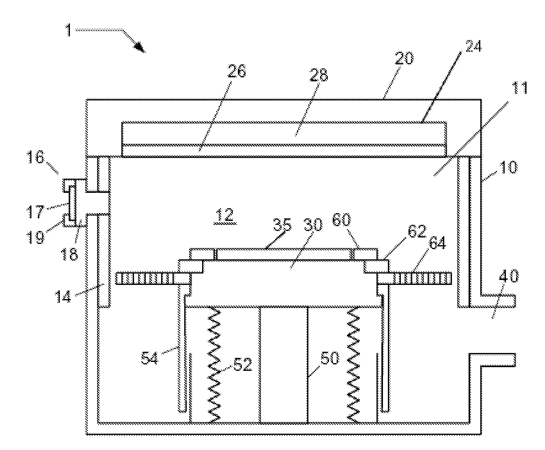
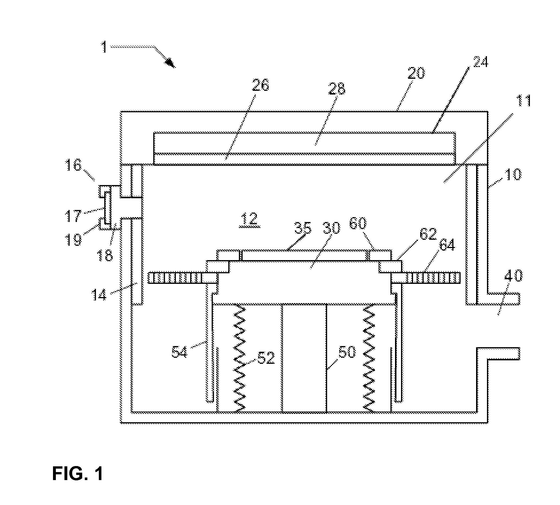
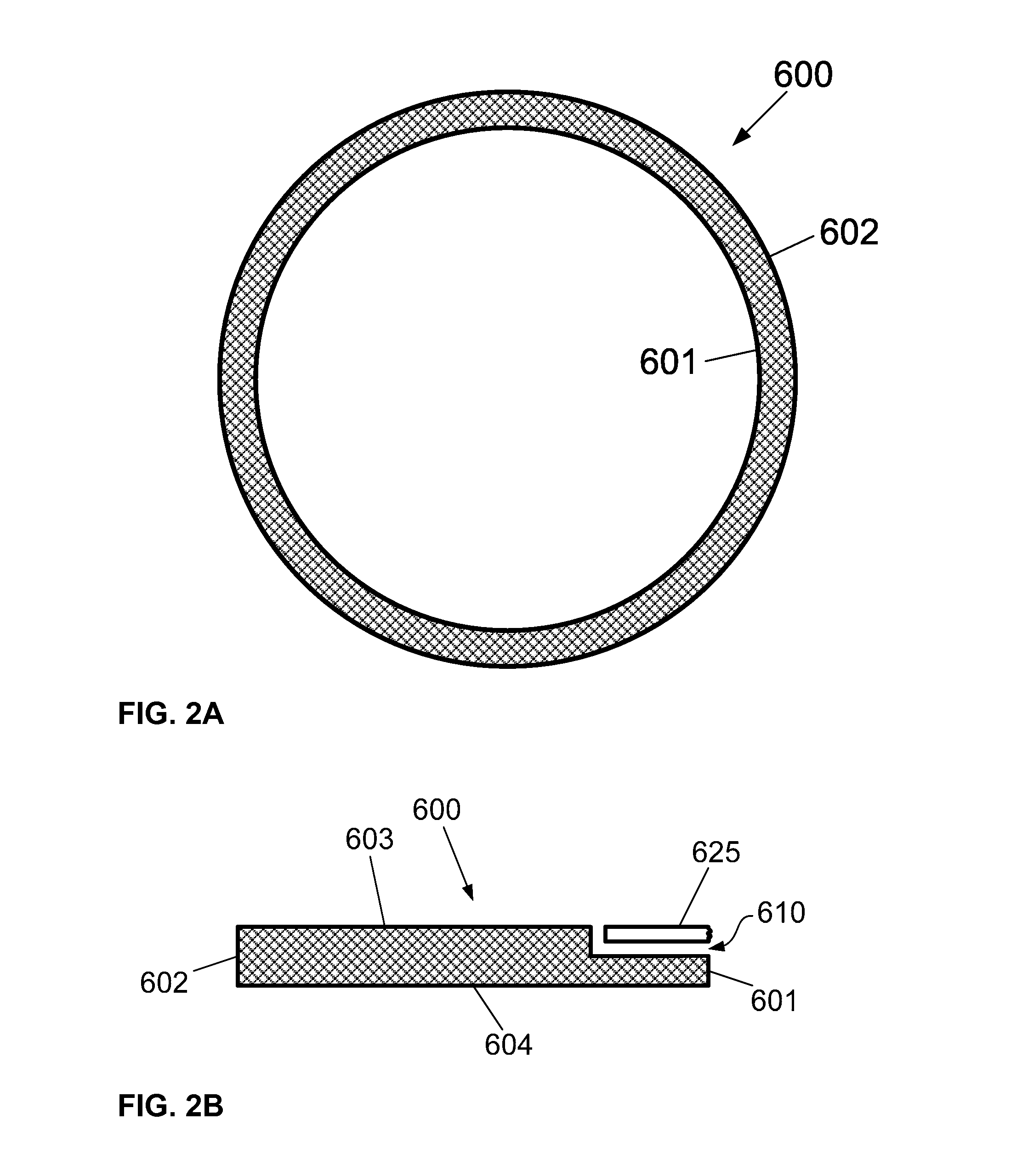
[0015]A focus ring for use in a plasma processing system is disclosed in various embodiments. However, one skilled in the relevant art will recognize that the various embodiments may be practiced without one or more of the specific details, or with other replacement and / or additional methods, materials, or components. In other instances, well-known structures, materials, or operations are not shown or described in detail to avoid obscuring aspects of various embodiments of the invention. Similarly, for purposes of explanation, specific numbers, materials, and configurations are set forth in order to provide a thorough understanding of the invention. Nevertheless, the invention may be practiced without specific details. Furthermore, it is understood that the various embodiments shown in the figures are illustrative representations and are not necessarily drawn to scale.

[0016]Reference throughout this specification to “one embodiment” or “an embodiment” means that a particular feature...


PUM

PropertyMeasurementUnit
sizeaaaaaaaaaa
sizeaaaaaaaaaa
frequencyaaaaaaaaaa

Abstract

A high resistivity silicon carbide focus ring for use in a plasma etching system is described. The focus ring comprises an upper surface, a lower surface, an inner radial edge, and an outer radial edge, and is configured to surround a substrate on a substrate holder in a plasma processing system. The focus ring comprises high resistivity silicon carbide having a resistivity greater than or equal to about 100 ohm-cm.

Description

BACKGROUND OF THE INVENTION[0001]1. Field of Invention[0002]The invention relates to a focus ring for use in a plasma processing system and, more particularly, to a high resistivity silicon carbide focus ring for use in a plasma etching system.[0003]2. Description of Related Art[0004]The fabrication of integrated circuits (IC) in the semiconductor industry typically employs plasma to create and assist surface chemistry within a vacuum processing system necessary to remove material from and deposit material to a substrate. In general, plasma is formed within the processing system under vacuum conditions by heating electrons to energies sufficient to sustain ionizing collisions with a supplied process gas. Moreover, the heated electrons can have energy sufficient to sustain dissociative collisions and, therefore, a specific set of gases under predetermined conditions (e.g., chamber pressure, gas flow rate, etc.) are chosen to produce a population of charged species and chemically reac...

Claims


Application Information

Patent Timeline
Patent Type & Authority Applications(United States)
IPC IPC(8): C23F1/08
CPCH01J37/32642H01J37/32623
Inventor URAKAWA, MASAFUMIKO, AKITERU
Owner TOKYO ELECTRON LTD
Why Eureka
Try Eureka