Restrained pipe joining system for plastic pipe

a coupling and plastic pipe technology, applied in the direction of hose connection, coupling, mechanical apparatus, etc., can solve the problems of limited success, reducing pipe wall strength, and addressing the limitation of pipe wall thickness, so as to improve the dimensional precision of the components

Active Publication Date: 2009-06-18
S & B TECHN PRODS
View PDF99 Cites 19 Cited by
  • Summary
  • Abstract
  • Description
  • Claims
  • Application Information

AI Technical Summary

Benefits of technology

[0026]In a particularly preferred version of the invention, the circumferential recess which is provided in the belled pipe end has a leading wall region, a trailing wall region and a bottom wall. A series of circumferentially spaced teeth are provided on the inner circumferential surface of the casing member which are alignable with a second circumferential groove provided on the exterior surface of the mating male spigot pipe end for receiving and engaging the casing member teeth. The location of the second circumferential groove and the casing member teeth are indexed a calculated distance from the trailing wall region of the circumferential recess. The engagement of the casing member teeth in the second circumferential groove provided on the exterior surface of the mating spigot pipe end assures the correct alignment of the circumferential recess and bore of the belled pipe end, with the bore in the casing member and the first groove in the mating male pipe member for proper receipt of the flexible key strap during assembly of the pipe joint.
[0027]In those versions of the invention using both a ring shaped casing member and an adjacent sealing elastomeric gasket, the casing member and gasket are

Problems solved by technology

It is well understood that, by definition, machining a groove into interior surface of the belled pipe end reduces wall thickness, thereby reducing pipe wall strength.
U.S. Pat. No. 6,325,424 describes a sealing

Method used


Image

  • Restrained pipe joining system for plastic pipe
  • Restrained pipe joining system for plastic pipe
  • Restrained pipe joining system for plastic pipe

Examples


Embodiment Construction

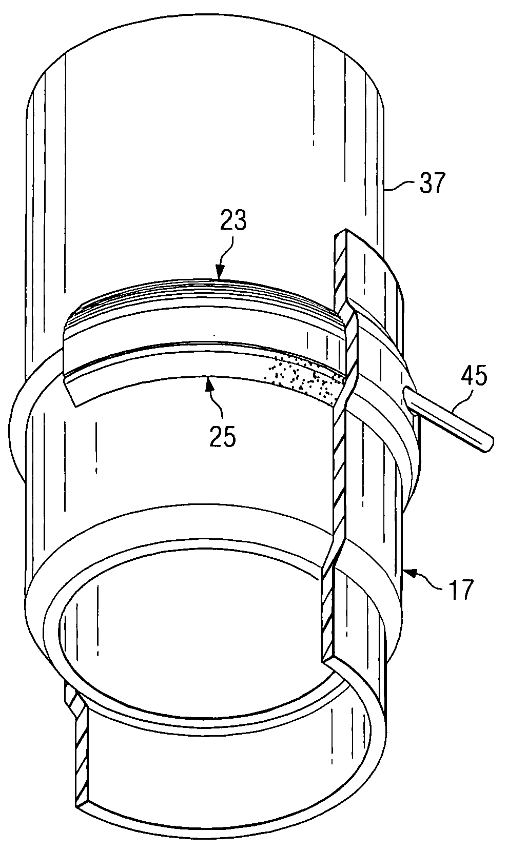
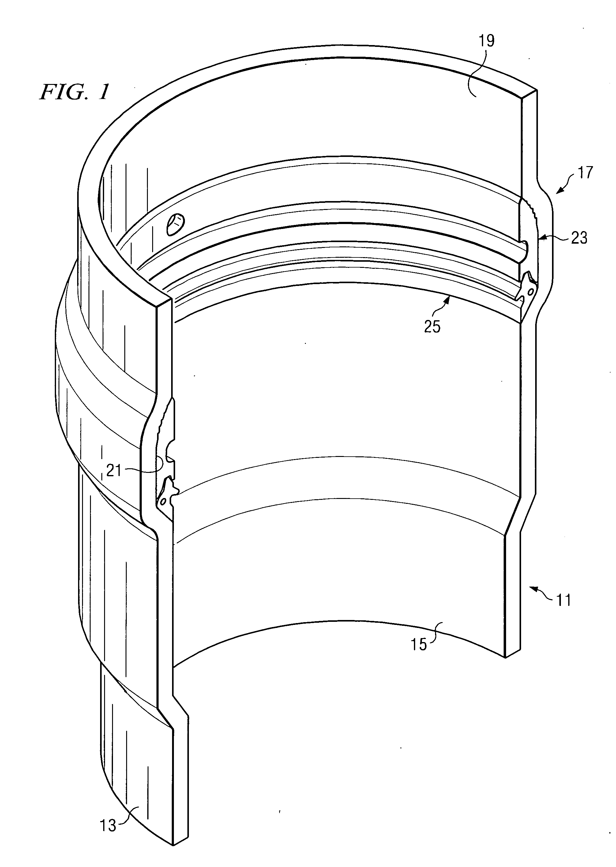
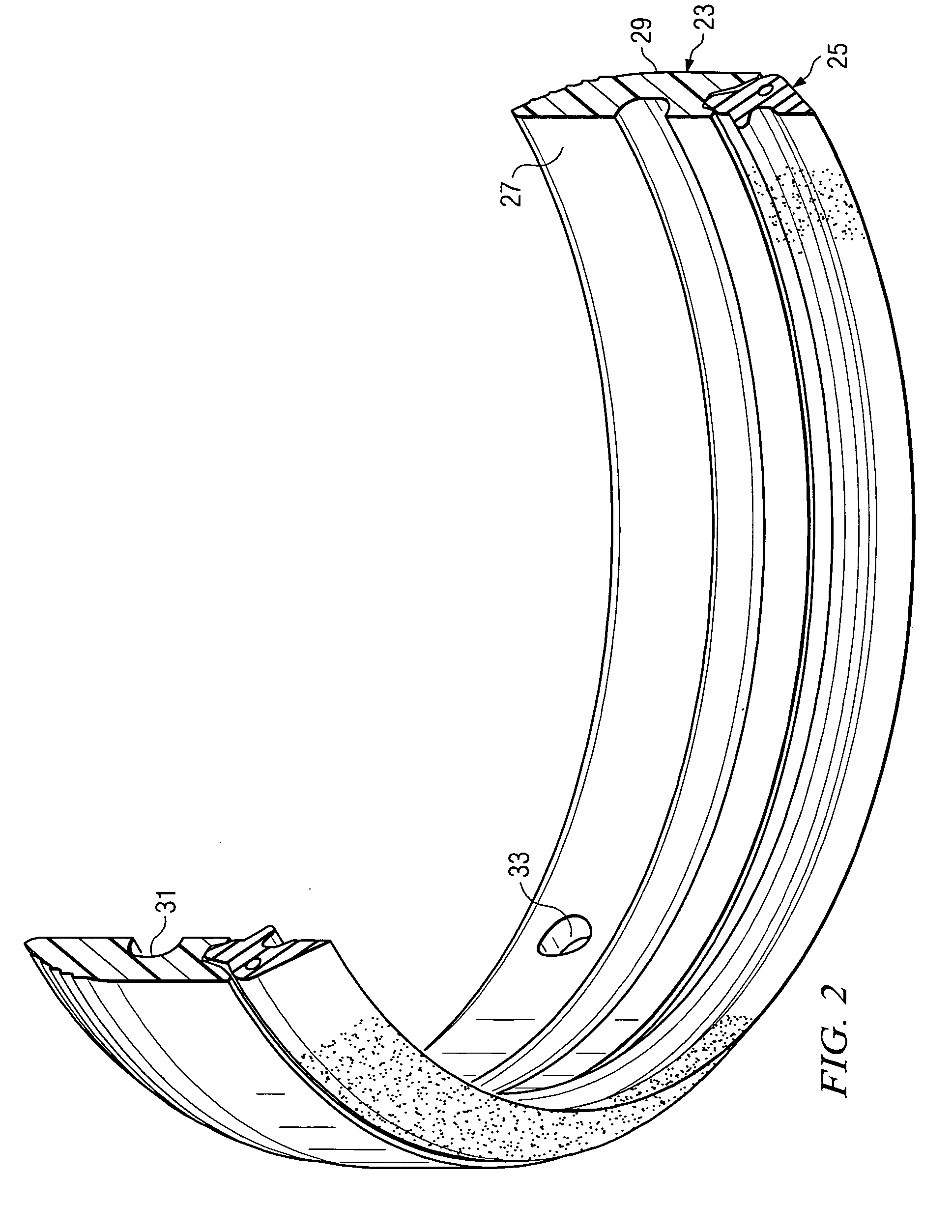
[0040]In a first aspect, the present invention uses an integrally formed recess in a female, belled pipe end which recess receives a special ring shaped casing member. The casing member has a groove formed on the inner circumference thereof which is aligned with a circumferential groove which is machined on the outside, outwardly facing surface of the mating male spigot pipe end. A bore is drilled through the female bell end and through the casing member and forms a canal type passageway when the bores and grooves in the casing member and mating spigot pipe end are all aligned. A locking key strap can be inserted through the bore drilled in the female belled pipe end and into the canal of the aligned grooves and be passed around the circumference of the pipe to form a secure joint.

[0041]While the following discussion uses the example of two “pipe sections” being joined in a straight run of pipeline or conduit, it will be understood that the principles of the invention can also be us...


PUM

PropertyMeasurementUnit
Flexibilityaaaaaaaaaa
Distanceaaaaaaaaaa

Abstract

A restrained pipe joining system is shown comprising male and female ends each having aligned circumferential grooves which form a canal for passage of a locking key strap. During manufacture, the female belled end is sequentially formed over a Rieber style gasket and then over a ring shaped casing member having an inner circumferential groove formed on its inner circumferential surface. Preferably, the ring shaped casing has circumferentially spaced teeth that act as a pipe stop in cooperation with an outer circumferential groove on the male spigot to index the pipes to be coupled.

Description

BACKGROUND OF THE INVENTION[0001]1. Field of the Invention[0002]The present invention relates generally to a restrained joint for coupling plastic pipe and, more specifically, to an improved belling process for the integral manufacture of such a restrained joint in the socket end of a thermoplastic pipe, fitting or coupling.[0003]2. Description of the Prior Art[0004]A variety of piping systems are known for the conveyance of fluids which employ elastomeric type sealing rings or gaskets. The pipes used in such systems may be formed of PVC, polyolefins such as PE and PP, ductile iron, concrete, clay, fiberglass, steel, cast iron, fiberglass / cement reinforced pipes and such metals as aluminum and copper. At the present time, pipes formed of thermoplastic materials, including PVC and polyethylene, are increasingly preferred for use in new pipeline installations for below ground pressure piping such as might be encountered in municipal water systems.[0005]In forming a joint between therm...

Claims


Application Information

Patent Timeline
IPC IPC(8): F16L47/12
CPCF16L37/148
Inventor STEINBRUCK, KEITH
Owner S & B TECHN PRODS
Why Eureka
Try Eureka