Circuit and associated method for reducing power consumption in an a power transformer

a power transformer and circuit technology, applied in the field of power conservation, can solve the problems of significant energy consumption, instantaneous power loss, and resistive loss in the primary coil of the transformer, and achieve the effect of preventing current loss, substantially reducing or eliminating unnecessary power consumption in the power transformer

Inactive Publication Date: 2009-06-18
AVAGO TECH INT SALES PTE LTD
View PDF18 Cites 54 Cited by
  • Summary
  • Abstract
  • Description
  • Claims
  • Application Information

AI Technical Summary

Benefits of technology

[0008]According to one aspect of the invention, a second switching device is used to further isolate the power transformer/rectifier. In one embodiment, the second switching device is coupled to an output of the power transformer/rectifier to prevent current losses in the secondary windings ...

Problems solved by technology

Losses such as resistive losses in the transformer primary coil will consume energy.
While instantaneous power losses are low, significant energy consumption accrues over time.
While these switch mode supplies can lead to more efficient power usage than, for example, a voltage divider in a dimmer switch, they suffer from being frequently m...

Method used


Image

  • Circuit and associated method for reducing power consumption in an a power transformer
  • Circuit and associated method for reducing power consumption in an a power transformer
  • Circuit and associated method for reducing power consumption in an a power transformer

Examples


example

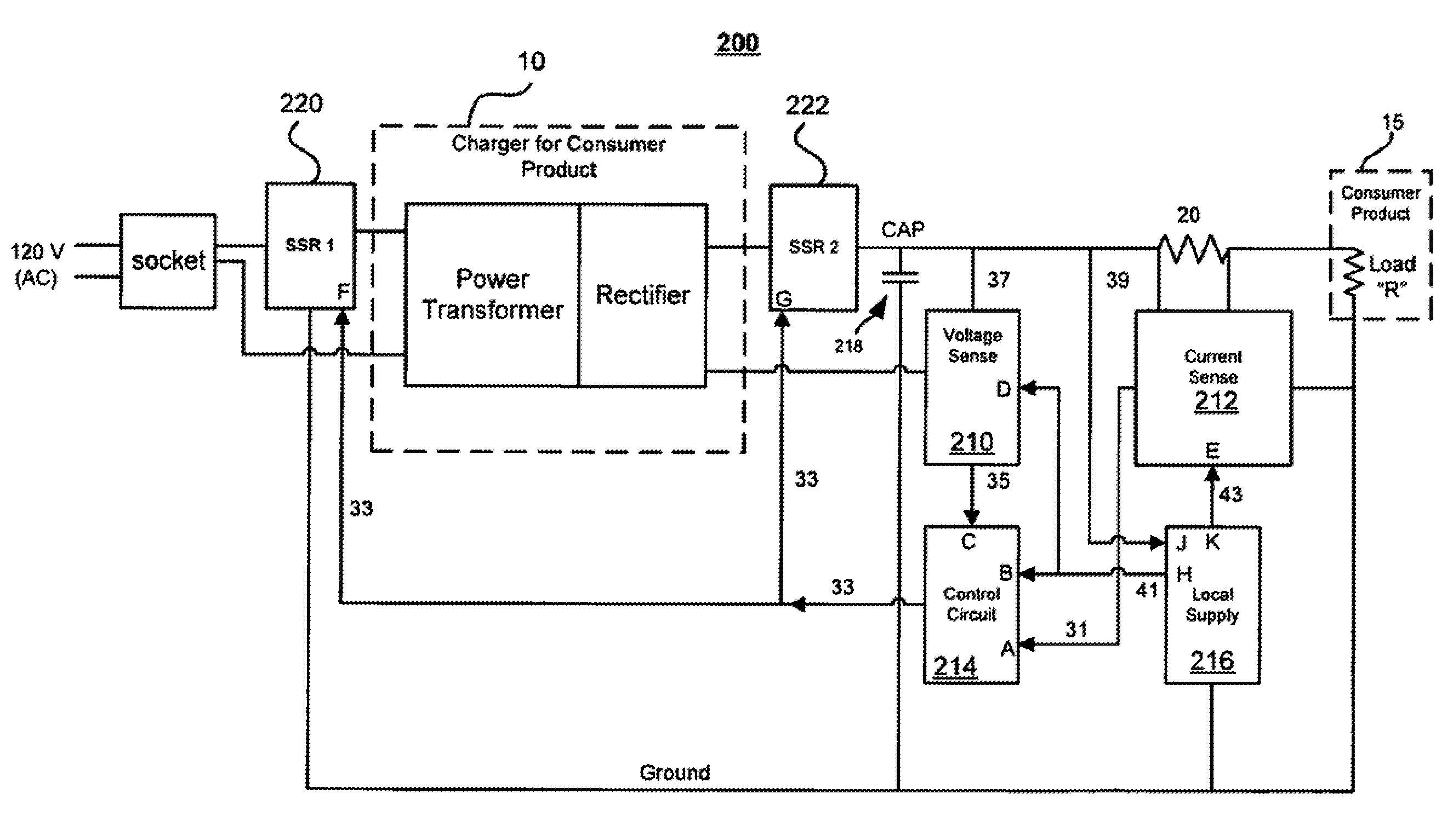
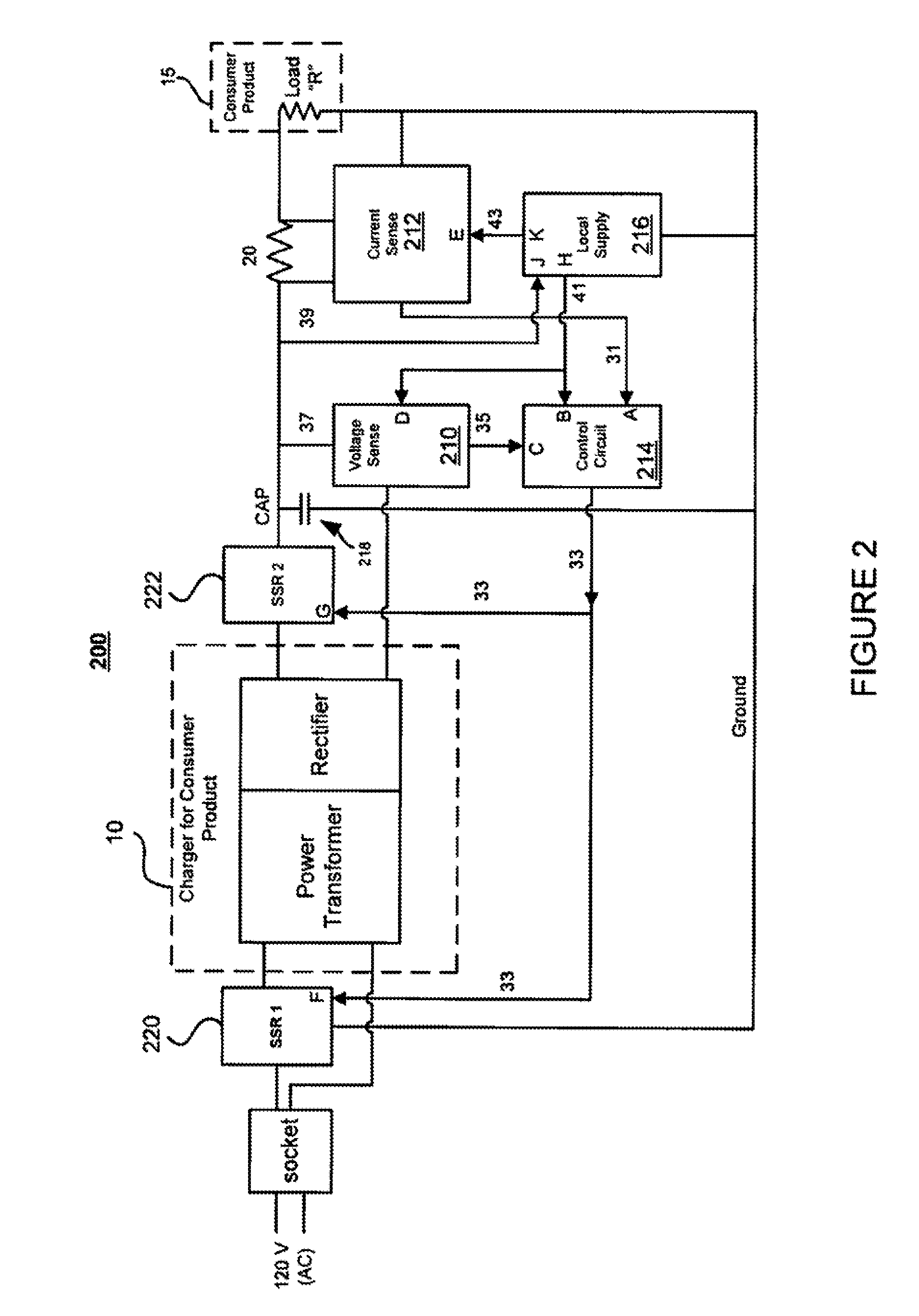
[0035]With reference now to FIG. 3, there is shown, by way of example, a method for reducing power consumption in a power transformer, typically incorporated into a charger 10 of a consumer device 15.

[0036]Prior to time T0: It is assumed that the relays 220, 222 have been previously closed and that super capacitor 218 is sufficiently charged to some nominal voltage level (e.g., 5V).

[0037]At time T0: load “R” of consumer product 15 is removed, as sensed by current sense module 214, which sends an output signal 301 to the control circuit 214. Control circuit 214 sends signal 307 to the relays 220, 222 to open.

[0038]From time T0 moving forward, the voltage on super-capacitor 218 slowly drains to maintain the other modules in an operating state while the relays 220, 222, remain open.

[0039]At time T1: The voltage on super-capacitor 218 reaches a pre-determined threshold level, V-low thresh. Voltage sense module 218 senses this condition and outputs signal 305 to the control circuit 214. ...


PUM


Abstract

A method and circuit is provided for reducing power consumption in a power transformer, typically incorporated into an electrical or electronic device such as a consumer device. In an embodiment, a detection/isolation circuit is coupled to an input of a power transformer/rectifier via a switching device. The switching device can be, for example, a solid state relay. The detection/isolation circuit is configured to sense the occurrence of no-load conditions in the power transformer and responsively disengage the power transformer from a coupled source of power (e.g., wall outlet) via the coupled switching device.

Description

FIELD OF THE INVENTION[0001]The present invention relates to the field of power conservation. In particular, the present invention relates to a circuit and associated method for preventing unnecessary energy consumption in a power transformer of electrical and electronic devices under no-load or low-load conditions.BACKGROUND OF THE INVENTION[0002]Power transformers and ‘chargers’ are used to power many office and household electronic and electrical devices. They operate by shifting incoming AC wall power to different, usually lower, voltage levels, often using a coil transformer. The coil on the input side is referred to as the primary winding and coil on the output side is referred to as the secondary winding. The secondary winding of a coil transformer is typically followed by a converter, which changes the AC transformer output into a DC signal.[0003]When a device on the secondary side of the transformer or charger requires power, it loads the transformer / charger output. However...

Claims


Application Information

Patent Timeline
IPC IPC(8): H02M7/02
CPCH02J2009/007H02J9/005H02J9/007Y04S20/20Y02B70/30
Inventor FOUQUET, JULIE ELIZABETHLUM, RICHARD K.K.BAUMGARTNER, RICHARD A.
Owner AVAGO TECH INT SALES PTE LTD
Why Eureka
Try Eureka