Non-contact method and apparatus for hardness case depth monitoring

a non-contact, hardness case technology, applied in the direction of instruments, weather/light/corrosion resistance, optical radiation measurement, etc., can solve the problem of not being suitable for industrial on-line volume inspection

Inactive Publication Date: 2009-06-18
WANG CHINHUA +1
View PDF15 Cites 15 Cited by
  • Summary
  • Abstract
  • Description
  • Claims
  • Application Information

AI Technical Summary

Problems solved by technology

The current industrial standard technique for these measurements is micro-indentation, which is destructive and time consuming, and therefore not suitable for the need of industrial on-line volume inspection.

Method used


Image

  • Non-contact method and apparatus for hardness case depth monitoring
  • Non-contact method and apparatus for hardness case depth monitoring
  • Non-contact method and apparatus for hardness case depth monitoring

Examples


third embodiment

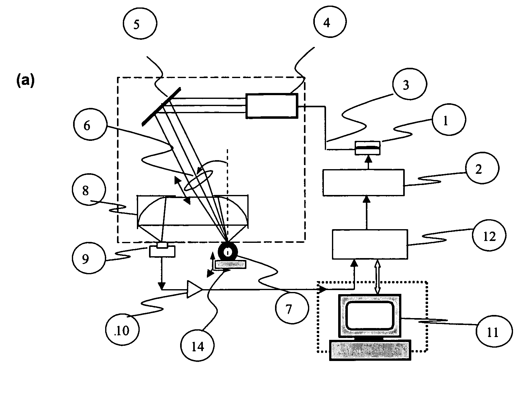
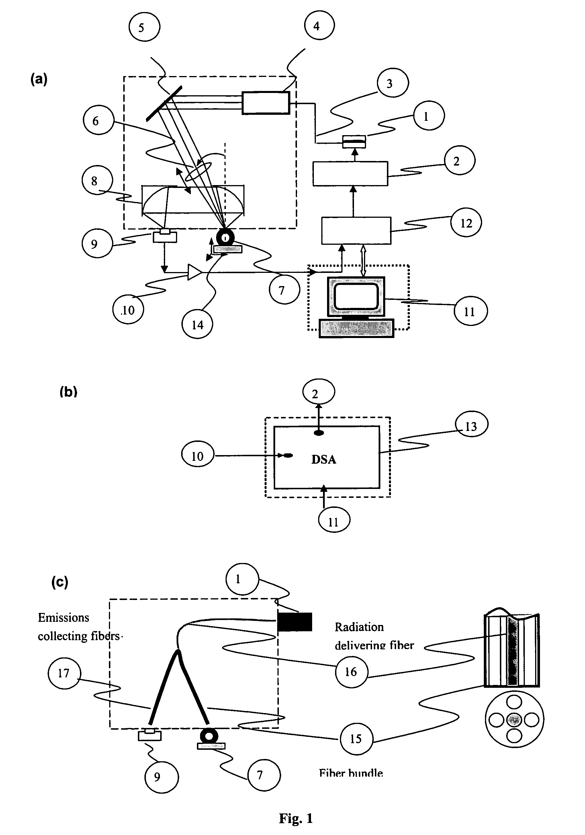
[0028]A schematic diagram of possible embodiments of an instrument for hardness case depth monitoring is shown in FIGS. 1a, 1b, and 1c. The excitation source is a high power semiconductor laser 1 capable of heating the material under examination. The laser power output was modulated by using a current driver 2 controlled by a personal computer 11 resulting in a harmonic energy source or beam 3 that is directed using an expander 4 a mirror 5 and lens 6 onto the sample 7. The beam was focused or expanded depending on the measurement scheme, and then impinged onto the surface of the sample with a spot size between 1 and 22 mm by adjusting the position of the converging lens 6. A pair of off-axis paraboloidal mirrors, 8 are aligned with the focal point coincident with that of the laser beam and used to collect emitted IR photons from the sample. The collected IR emissions are focused onto a detector 9 after being passed through a filter that allows Planck-mediated thermal infrared emiss...


PUM

PropertyMeasurementUnit
frequencyaaaaaaaaaa
sizeaaaaaaaaaa
spot sizeaaaaaaaaaa

Abstract

There is provided a method and apparatus to monitor hardness using laser infrared photothermal radiometry. The emphasis is on the ability of this invention to monitor in a non-contact and non-destructive manner the hardness case depth of industrially heat treated steels. The present invention provides a method and apparatus comprising signal generation and analysis as well as instrumental hardware configurations based on the physical principle of photothermal radiometry. The method comprises (a) irradiating the sample surface with an excitation source of suitable emission wavelength and intensity. (b) producing periodic frequency pulses of the laser beam by means of a modulator in the appropriate frequency range (but not confined to) 0.1-100000 Hz. (c) passing the emitted beam through appropriate optics for beam conditioning (d) splitting the incident beam in two beams using a beam-splitter (e) focusing one of the beams onto a photodiode connected to a lock-in amplifier referenced to the modulator frequency to monitor laser power fluctuations (f) directing the second beam normal or at an angle to the surface of the sample (g) directing the generated infrared emissions from the sample surface to an infrared detector connected to another lock-in amplifier also referenced to the modulator frequency (h) recording the signals obtained from both lock-in amplifiers by a computer (i) processing the obtained signals through proprietary software and pre-calibration curves.

Description

FIELD OF INVENTION[0001]The present invention relates to a non-contact, non-destructive method and apparatus to monitor hardness case depth of industrially heat treated steels using laser infrared photothermal radiometry.BACKGROUND OF THE INVENTION[0002]Hardness and case depth measurements are the most important parameters for the quality monitoring of case-hardened steel products and the heat treating process. The current industrial standard technique for these measurements is micro-indentation, which is destructive and time consuming, and therefore not suitable for the need of industrial on-line volume inspection. There have been continuous efforts to search for new methods for evaluating hardness and case depth in a non-contact and non-destructive fashion. In recent years, photothermal techniques have shown strong potential for non-contact and remote hardness and case depth evaluation. A number of photothermal applications to hardness measurements in metals have been reported in ...

Claims


Application Information

Patent Timeline
Patent Type & Authority Applications(United States)
IPC IPC(8): G01N3/40
CPCG01N2203/0682G01N3/54
Inventor WANG, CHINHUAGARCIA, JOSE A.
Owner WANG CHINHUA
Why Eureka
Try Eureka