
Apparatus and method for measuring characteristic and chip temperature of LED

a technology of characteristic and chip temperature, applied in the field of apparatus and a method for measuring characteristic and chip temperature of light emitting diodes, can solve the problems of high temperature of led chips, difficult to measure junction temperature of led chips with a direct measurement, and increase in density of heating generating density. achieve the effect of rapid temperature variation

Inactive Publication Date: 2009-06-18
IND TECH RES INST
View PDF15 Cites 46 Cited by
  • Summary
  • Abstract
  • Description
  • Claims
  • Application Information

AI Technical Summary

Benefits of technology

[0010]Accordingly, the present invention is directed to an apparatus and a method for measuring a characteristic and a chip temperature of an LED. The present invention applies a temperature control directly to the LED chip by thermal conduction, so as to rapidly achieve a stable temperature variation, and promptly measure a TSP of the LED chip.
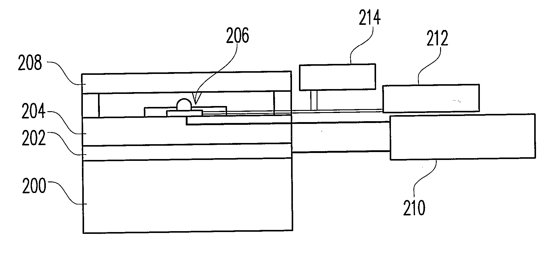
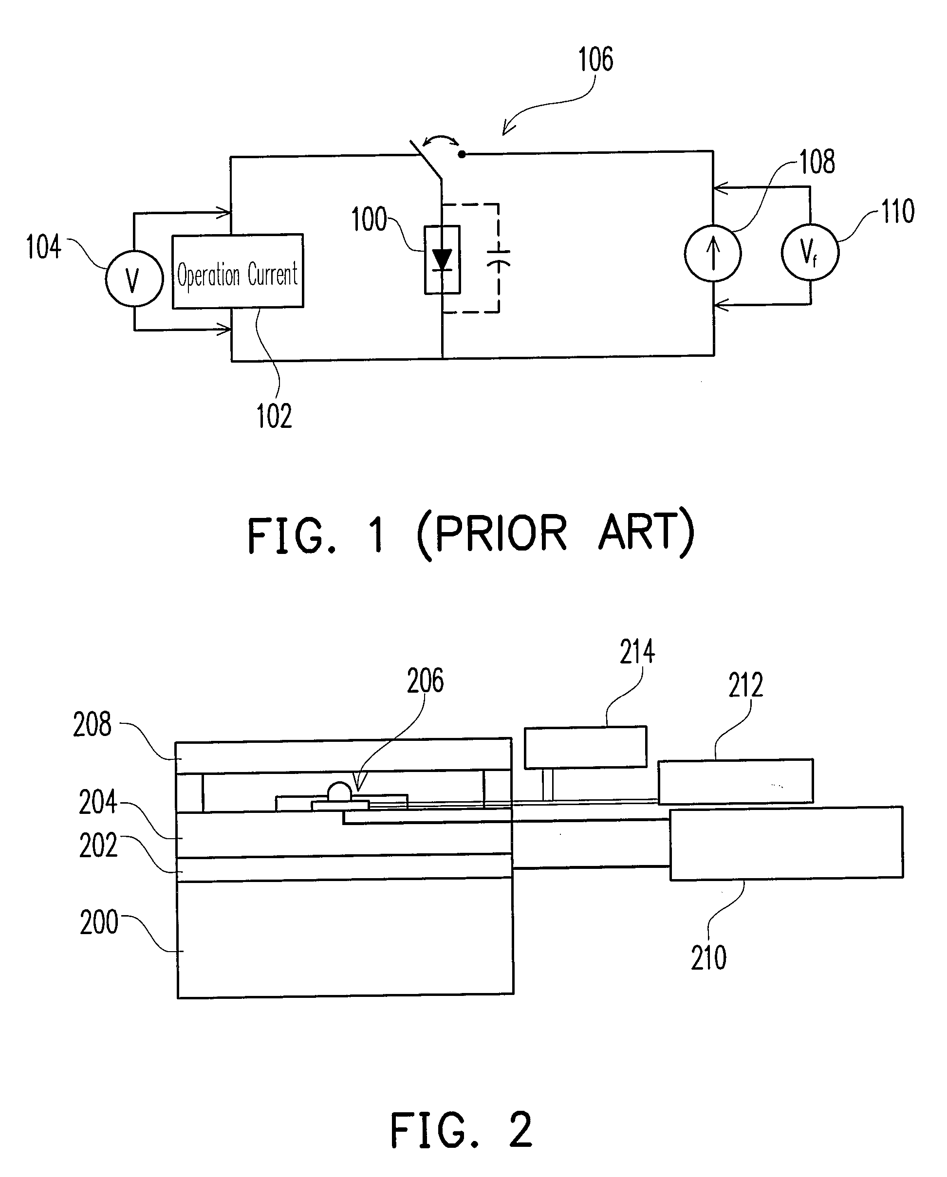
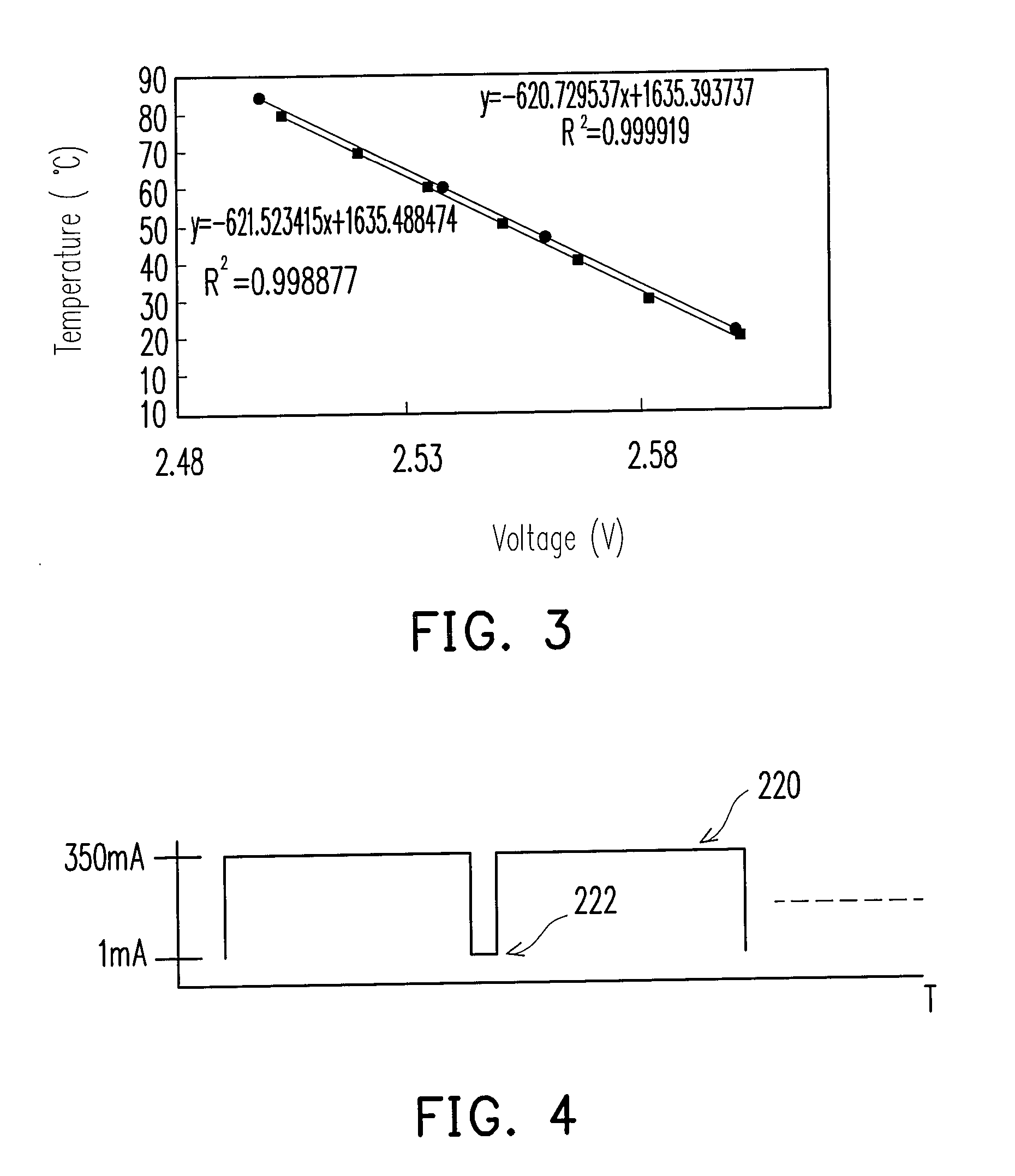
[0011]The present invention provides an apparatus for measuring a characteristic and a chip temperature of an LED. The apparatus includes a thermal conductive component, an LED chip, a temperature control unit, and a power-source and voltage-meter unit. The LED chip is disposed on the thermal conductive component. The temperature control unit is connected to the thermal conductive component for providing a temperature to the thermal conductive component, and therefore providing the temperature to the LED chip via the thermal conductive component. The power-source and voltage-meter unit provides a current to the LED chip, and measures a voltage value of the LED chip. Under a measurement mode, the current is featured with a current waveform having a high current level and a low current level which are alternatively changed, for applying to the LED chip. Measurements are taken respectively corresponding to the high current level and the low current level, and a correlation curve between the voltage and the temperature can at least be obtained with the results of measurement.
[0012]The present invention provides a method for measuring a characteristic and a chip temperature of an LED. The method includes providing a thermal conductive component, and providing an LED chip disposed on the thermal conductive component. A temperature is provided to the LED chip in thermal conductive type via the thermal conductive component. A current is applied to the LED chip. The current is featured with a current waveform having a high current level and a low current level which are alternatively varied. The method further includes measuring a correlation curve between a voltage and a temperature at either the high current level or the low current level.

Problems solved by technology

Unfortunately, under the situation that the light emitting efficiencies of the current LED chips is limited, most of the inputted power is converted into heat causing a drastic increase on heating generating density.
In such a way, the overheat problem is a bottleneck in technology development.
However, a junction of a packaged LED is encapsulated inside, and therefore the junction temperature of LED chip is difficult to measure with a direct measurement.
However, they are usually complicated, which often require the use of a metal-oxide semiconductor field effect transistor (MOSFET), or a rectifier diode, or even an OR logic circuit including at least two rectifier diodes.
As such, those conventional approaches of measuring the thermal resistance are all restricted because the measurement of the TSP requires a stable testing condition which correspondingly requires a relative long time for getting the temperature balanced.
Therefore, conventional approaches are not suitable for fast measurement of thermal resistances, optical characteristics of LEDs under different temperatures.
Currently, these are the difficult issues in measuring the LED characteristics.

Method used


Image

  • Apparatus and method for measuring characteristic and chip temperature of LED
  • Apparatus and method for measuring characteristic and chip temperature of LED
  • Apparatus and method for measuring characteristic and chip temperature of LED

Examples


Embodiment Construction

[0023]Reference will now be made in detail to the present preferred embodiments of the invention, examples of which are illustrated in the accompanying drawings. Wherever possible, the same reference numbers are used in the drawings and the description to refer to the same or like parts.

[0024]The present invention is adapted for obtaining a better result in complete, fast and accurate measurement of optical and thermal characteristics of an LED. The apparatus and method according to the present invention employ a thermal conductive type mechanism to directly heat the LED to a desired temperature, so as to allow a fast measurement of a TSP. The apparatus and the method further combine the measurement of optical characteristics, or even control of the substrate temperature or ambient temperatures. According to an aspect of the embodiment, the present invention may even further include a data acquisition (DAQ) card, so as to acquire more and accurate voltage values during a short switc...


PUM

PropertyMeasurementUnit
currentaaaaaaaaaa
currentaaaaaaaaaa
timeaaaaaaaaaa

Abstract

An apparatus for measuring a characteristic and a chip temperature of an LED includes a thermal conductive component. An LED chip is disposed on the thermal conductive component. A temperature control unit is connected to the thermal conductive component for providing a temperature to the thermal conductive component, and therefore providing the temperature to the LED chip via the thermal conductive component. A power-source and voltage-meter unit provides a current to the LED chip, and measures a voltage value of the LED chip. Under a measurement mode, the current is featured with a current waveform having a high current level and a low current level which are alternatively changed, for applying to the LED chip. Measurements are conducted respectively corresponding to the high current level and the low current level, and a correlation curve between the voltage and the temperature can be obtained with the results of measurement.

Description

CROSS-REFERENCE TO RELATED APPLICATION[0001]This application claims the priority benefit of Taiwan application serial no. 96147955, filed Dec. 14, 2007. The entirety of the above-mentioned patent application is hereby incorporated by reference herein and made a part of this specification.BACKGROUND OF THE INVENTION[0002]1. Field of the Invention[0003]The present invention generally relates to an apparatus and a method for measuring a characteristic and a chip temperature of a light emitting diode (LED).[0004]2. Description of Related Art[0005]Recently, benefited from the drastic development of the epitaxy technology, LED semiconductor technology has successfully improved the light emitting efficiency of LED chips. As such, LEDs are more widely used, for example in projection pens, and illuminations. LEDs are known as having advantages of small sizes, longer lifetime, no contamination, and low cost. In addition, LEDs have better optical characteristics such as good color saturation, ...

Claims


Application Information

Patent Timeline
Patent Type & Authority Applications(United States)
IPC IPC(8): G01K7/00
CPCG01K2217/00G01K7/01
Inventor DAI, MING-JILIU, CHUN-KAICHIEN, HENG-CHIEHYU, CHIH-KUANGKUO, SHENG-LIANG
Owner IND TECH RES INST
Learn More