Systems and methods for communication system control utilizing corrected forward error correction error location identifiers

a communication system and error location technology, applied in the field of communication systems, can solve the problems of limiting the utilization of the overall transmission system in the wavelength division multiplexed (wdm) network, affecting the accuracy of the transmission system, etc., to achieve the effect of maintaining error-free operation quickly

Active Publication Date: 2009-06-18
CIENA
View PDF3 Cites 9 Cited by
  • Summary
  • Abstract
  • Description
  • Claims
  • Application Information

AI Technical Summary

Benefits of technology

[0011]In various exemplary embodiments, the present invention provides systems and methods for communication system control utilizing corrected forward error correction (FEC) error location identifiers in multi-level modulation scheme systems. The present invention utilizes precise error correction information, available for each FEC block of a particular error correction code (including, but not limited to, block codes and concatenated block codes employing iterative decoding as well as convolutional codes (including turbo codes) and low-density parity-ch...

Problems solved by technology

Disadvantageously, binary modulation schemes provide a very poor spectral efficiency and limit overall transmission system utilization in wavelength division multiplexed (WDM) networks.
Disadvantageously, such high data rates are beyond current limits of the electronics and optics using a direct binary modulation scheme.
Multi-level amplitude modulation is also possible for optical communication systems, but is not very attractive for optical communication as it does not provide a high separation between adjacent levels, and is susceptibl...

Method used


Image

  • Systems and methods for communication system control utilizing corrected forward error correction error location identifiers
  • Systems and methods for communication system control utilizing corrected forward error correction error location identifiers
  • Systems and methods for communication system control utilizing corrected forward error correction error location identifiers

Examples


Embodiment Construction

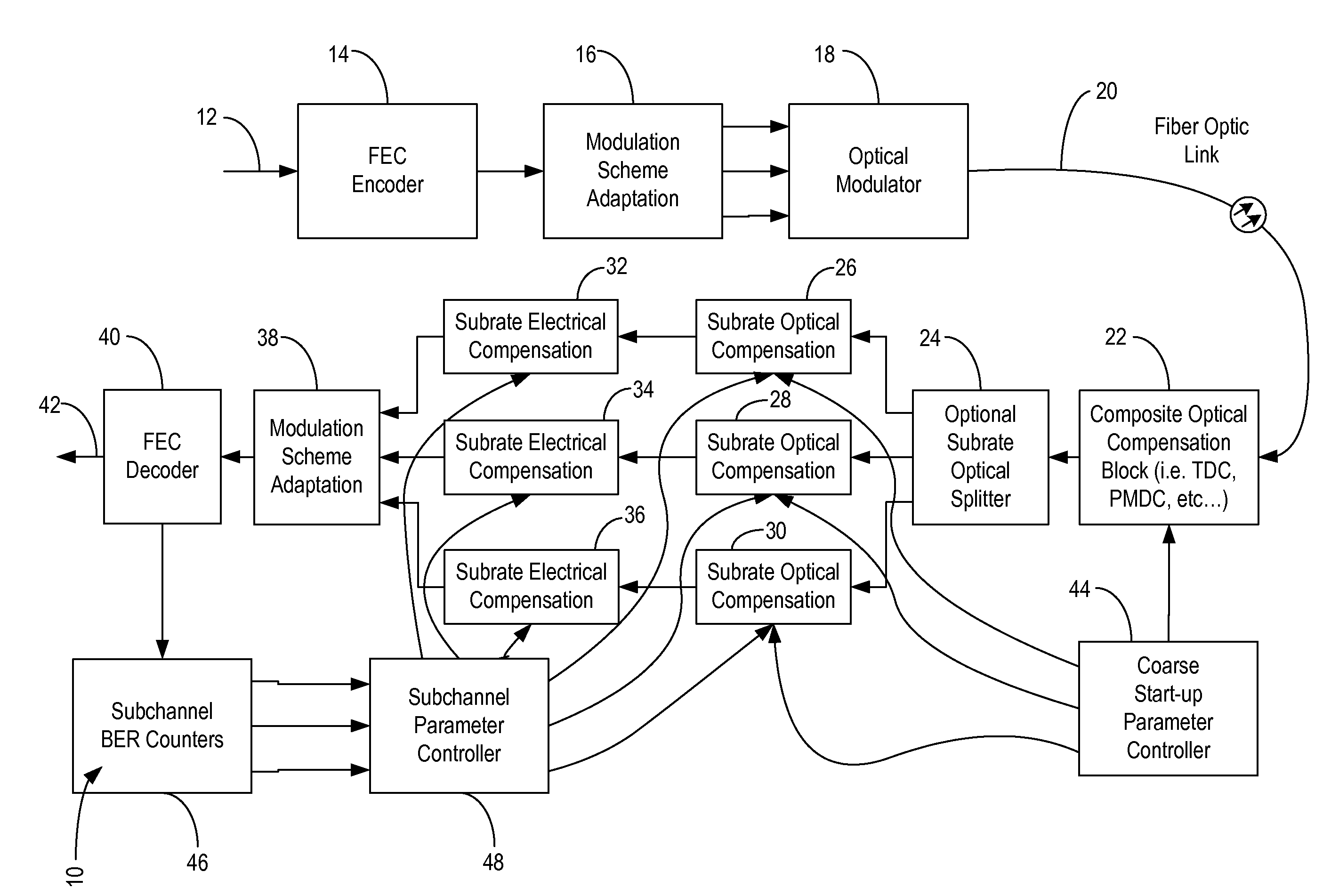
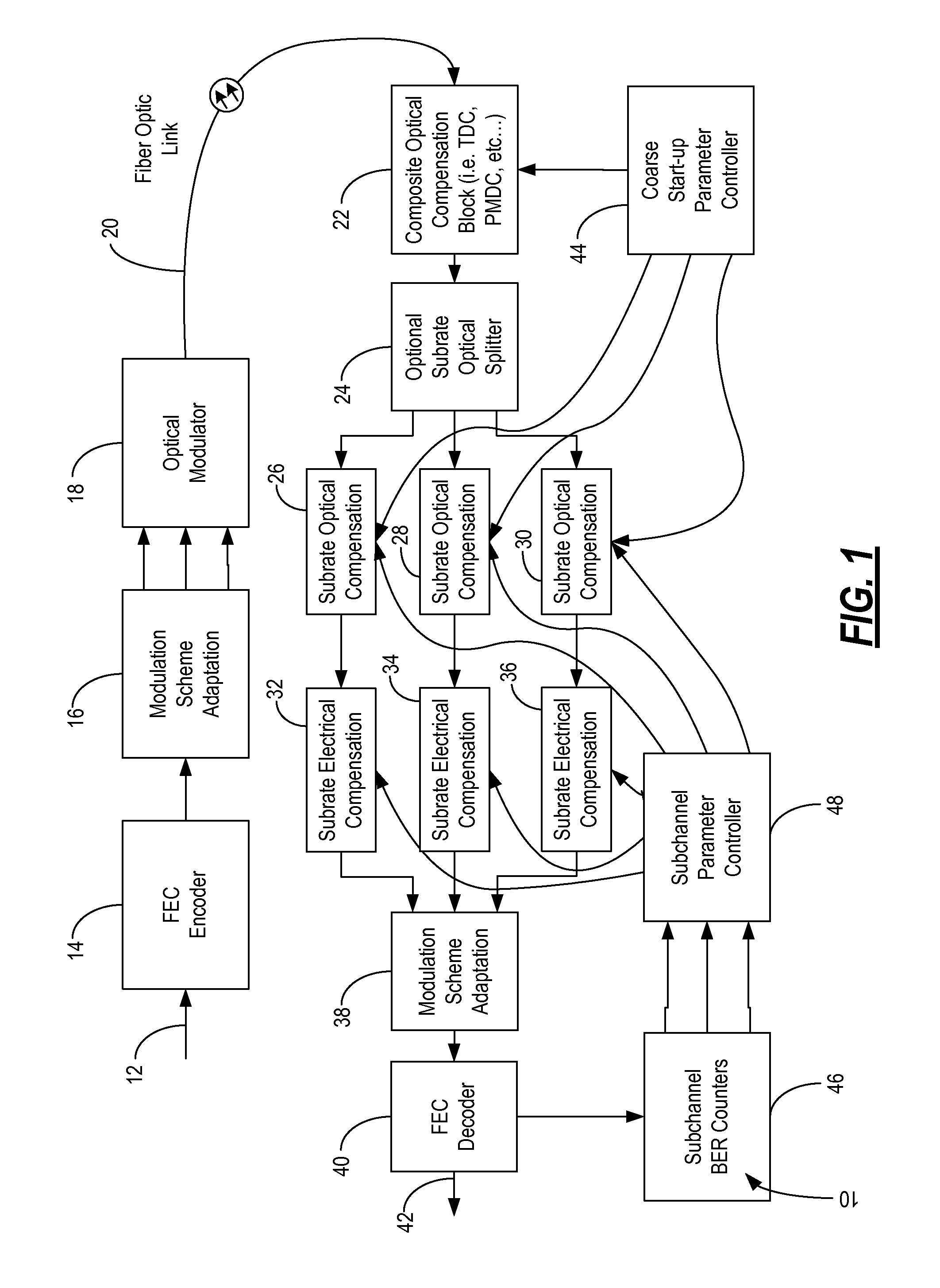
[0018]In various exemplary embodiments, the present invention provides systems and methods for communication system control utilizing corrected forward error correction (FEC) error location identifiers in multi-level modulation scheme systems. The present invention utilizes precise error correction information, available for each FEC block of a particular error correction code as a result of the FEC decoding process to provide feedback to close the loop for control of a demodulator (i.e., receiver). Each error location can be uniquely traced back to a particular sub-rate signal path, with running, post-FEC corrected BER (bit error rate) calculations generated on each sub-rate signal. Advantageously, this provides the ability to adjust receiver thresholds and various other parameters to achieve and maintain error-free operation quickly.

[0019]Referring to FIG. 1, a block diagram of a multi-level modulation communication system 10 is depicted according to an exemplary embodiment of the...


PUM


Abstract

The present invention provides systems and methods for communication system control utilizing corrected forward error correction (FEC) error location identifiers in multi-level modulation scheme systems. The present invention utilizes precise error correction information, available for each FEC block of a particular code (including, but not limited to, block codes and concatenated block codes employing iterative decoding as well as convolutional codes (including turbo codes) and low-density parity-check code (LDPC) class codes) used (e.g., Bose, Ray-Chaudhuri, Hocquenghem (BCH), Reed-Solomon, etc.), as a result of the FEC decoding process to provide feedback to close the loop for control of a demodulator (i.e., receiver). Each error location can be uniquely traced back to a particular sub-rate signal path, with running, post-FEC corrected BER (bit error rate) calculations generated on each sub-rate signal. Advantageously, this provides the ability to adjust thresholds and various other parameters to achieve and maintain error-free operation quickly.

Description

FIELD OF THE INVENTION[0001]The present invention relates generally to communication systems. More specifically, the present invention relates to communication system control utilizing corrected forward error correction (FEC) error location identifiers in multi-level modulation scheme systems.BACKGROUND OF THE INVENTION[0002]Communication systems utilize various modulation schemes depending on the particular medium, bandwidth, and information signal. To increase spectral efficiency, many communication systems utilize multi-level modulation schemes. For example, wireless, copper-based, and other communication systems can utilize orthogonal frequency-division multiplexing (OFDM), quadrature amplitude modulation (QAM), quadrature phase shift keying (QPSK), polarization multiplexing, and the like. Each of these modulation schemes transmits multiple bits per symbol. For example, QPSK scheme is attractive as it transmits two bits per symbol, thereby reducing signal baud (i.e. symbol) rate...

Claims


Application Information

Patent Timeline
IPC IPC(8): H04B10/06
CPCH04L1/005H04L1/0066H04L1/0059H04L1/0057
Inventor MATEOSKY, JOHN P.FRANKEL, MICHAEL Y.ARCHAMBAULT, JEAN-LUC
Owner CIENA
Why Eureka
Try Eureka