Hydrogen storage system for fuel cell vehicle

a fuel cell and hydrogen storage technology, applied in the direction of fuel cell details, electrical equipment, mechanical equipment, etc., can solve the problems of insufficient compact packaging, insufficient hydrogen storage, and disadvantages in system weight, price, and storage efficiency, and achieve low hydrogen release temperature, high hydrogen density, and high volumetric storage density.

Inactive Publication Date: 2009-06-18
HYUNDAI MOTOR CO LTD +1
View PDF4 Cites 31 Cited by
  • Summary
  • Abstract
  • Description
  • Claims
  • Application Information

AI Technical Summary

Benefits of technology

[0031]The present invention has been made in an effort to solve the above-described problems associated with prior art. The present invention is directed to a hydrogen storage system for a fuel cell system, in which both a commercially available hydrogen storag...

Problems solved by technology

At present, a high-pressure (35 MPa or 70 MPa) hydrogen storage system is used in fuel cell vehicles; however, it has a limitation in increasing the amount of hydrogen storage due to a low density of gaseous hydrogen.
That is, in order to store 5 Kg of hydrogen with a 35 MPa hydrogen storage system, a storage tank having an inner volume of about 215 L is required, which is inadequate for compact packaging of fuel storage system.
Moreover, in order to store 5 Kg of hydrogen with a 70 MPa hydrogen storage system, the required volume is about 125 L, which is considered more advantageous than the 35 MPa hydrogen storage system in terms of a vehicle package; however, it is disadvantageous in terms of system weight, price, and storage efficiency.
In the case where the hydrogen generating material in a slurry phase is used in a hydrogen generating system, since the hydrogen is produced mainly by hydrolysis, by-products are formed after the generation of hydrogen and it is difficult to dispose of the by-products from the system mounted in a vehicle.
They have an advantage in that the hydrogen release temperature is very low to the extent that heat generated from the fuel cell can be used for hydrogen release; however, there is ...

Method used


Image

  • Hydrogen storage system for fuel cell vehicle
  • Hydrogen storage system for fuel cell vehicle
  • Hydrogen storage system for fuel cell vehicle

Examples


Embodiment Construction

[0050]Reference will now be made in detail to the preferred embodiments of the present invention, examples of which are illustrated in the drawings attached hereinafter, wherein like reference numerals refer to like elements throughout. The embodiments are described below so as to explain the present invention by referring to the figures.

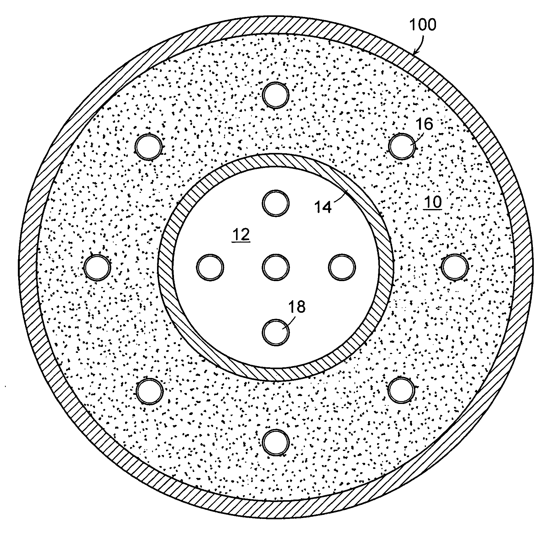
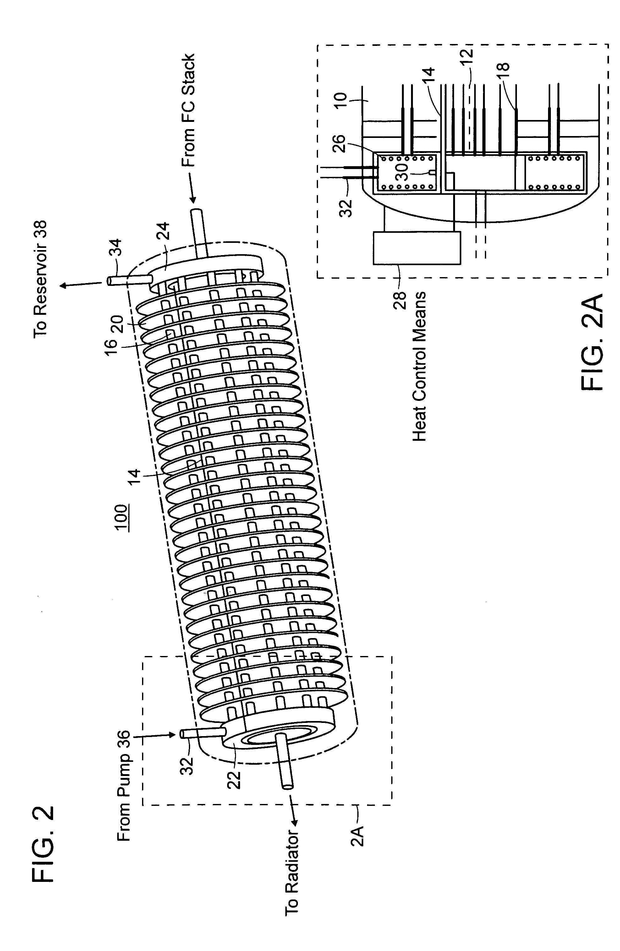
[0051]FIG. 1 is a cross-sectional view showing a main part of a hydrogen storage tank of a hydrogen storage system for a fuel cell vehicle in accordance with a preferred embodiment of the present invention.

[0052]As show in FIG. 1, a first storage alloy powder 10, which can release hydrogen at a relatively high temperature, is filled in an outer space V1 of an MH hydrogen storage tank 100 in a cylindrical shape, and a second storage alloy powder 12, which can release hydrogen only with heat generated from a fuel cell stack 300, i.e., which can release hydrogen at a low temperature, is filled in an inner space V2 thereof.

[0053]In particular, the first...


PUM


Abstract

The present invention provides a hydrogen storage system using a metal hydride (MH), which can increase volumetric storage density of hydrogen and total hydrogen storage capacity and improve system packaging.
For this purpose, the present invention provides a hydrogen storage system for a fuel cell vehicle, the hydrogen storage system including: an outer space filled with a first storage alloy powder that is able to release hydrogen at a high temperature; an inner space filled with a second storage alloy powder that is able to release hydrogen only with heat generated from a fuel cell stack; a metal filter disposed between the outer and inner spaces so as to divide the outer and inner spaces; a second heat exchange tube provided between the fuel cell stack and a radiator to constitute a cooling loop and arranged along a longitudinal direction of the inner space; and an independent heat exchange loop independently connected to the outer space for the hydrogen release of the first storage alloy powder.

Description

CROSS-REFERENCE TO RELATED APPLICATION[0001]This application claims under 35 U.S.C. §119(a) the benefit of Korean Patent Application No. 10-2007-0129933 filed Dec. 13, 2007, the entire contents of which are incorporated herein by reference.BACKGROUND[0002](a) Technical Field[0003]The present invention relates to a hydrogen storage system for a fuel cell vehicle. More particularly, the present invention relates to a hydrogen storage system using a metal hydride (MH), which can increase volumetric storage density of hydrogen and total hydrogen storage capacity and improve system packaging.[0004](b) Background Art[0005]One of the essential requirements for commercializing fuel cell vehicles is to achieve a sufficient driving range, without refueling, corresponding to that of an internal combustion engine vehicle.[0006]For example, in order to achieve a driving range of up to 300 miles on one fueling, a vehicle has to store hydrogen not less than about 5 kg.[0007]At present, a high-pres...

Claims


Application Information

Patent Timeline
IPC IPC(8): H01M8/18
CPCY02E60/321F17C11/005Y02E60/32Y02E60/50H01M8/02H01M8/04
Inventor LEE, HOON HEEKIM, HYUNG KIHWANG, KI HO
Owner HYUNDAI MOTOR CO LTD
Why Eureka
Try Eureka