Gas filling apparatus

a gas filling and apparatus technology, applied in liquid handling, packaging goods, transportation and packaging, etc., can solve the problems of inaccessible dustless environment, insufficient gas filling, failure of gas filling,

Active Publication Date: 2009-06-25
GUDENG EQUIP CO LTD
View PDF32 Cites 8 Cited by
  • Summary
  • Abstract
  • Description
  • Claims
  • Application Information

AI Technical Summary

Benefits of technology

[0009]Therefore, one objective of the present invention is to provide a gas filling apparatus with a set of air feed source route that is became a closed loop and facilitates stabilizing an overall gas pressure in the set of air feed source route.
[0010]Another objective of the present invention is to provide a gas filling apparatus with a set of air feed source route formed as a closed loop that facilitates equalizing the pressure and flow rate of gas at all extremes of the set of air feed source route.
[0011]Another objective of the present invention is to provide a gas filling apparatus with a pressure stabilizer that facilitates adjusting the pressure and flow rate of gas in the set of air feed source route so as to equalize pressure and flow rate of gas at all extremes of the set of air feed source route.
[0012]Another objective of the present invention is to provide a gas filling apparatus having a first sensing device that senses the pressure and flow rate of gas within set of air feed source route and communicates a signal to a pressure stabilizer that facilitates adjusting the pressure and flow rate so that the gas filling apparatus can control the pressure and flow rate of gas automatically in set of air feed source route.
[0015]Still another objective of the present invention is to provide a gas filling apparatus with a flow rate regulator to adjust the gas flow rate that enters into the storage apparatus so as to prevent an article in the storage apparatus from damaged by exploded gas.

Problems solved by technology

However, absolute dustless environment is inaccessible even in the known clean rooms.
Such conventional gas filling apparatus is disadvantageous by the excessive gas pressure at the front gas outlets causing an excessive gas flow to be filled into the storage apparatuses that brings the risk of damaging the reticle or semiconductor elements in the storage apparatuses and the poor gas flow in company with the poor gas pressure at the rear gas outlets that possibly renders insufficient gas filling or even failed gas filling.
As a result, though the storage apparatuses are attached to the identical gas filling apparatus, the undesired gas pressure distribution causes irregular and unmanageable gas flows for the respective storage apparatuses and therefore results in increased manufacturing and managing costs.

Method used


Image

  • Gas filling apparatus
  • Gas filling apparatus
  • Gas filling apparatus

Examples


Embodiment Construction

[0024]While the present invention discloses a gas filling apparatus with a closed loop, it is to be stated first of all that the detailed manufacturing or processing procedures of the mentioned reticles, semiconductor elements, storage apparatuses and gas filling apparatuses relay on known technology and need not be discussed at length herein. Meantime, while the accompanying drawings are provided for purpose of illustration, it is to be understood that the components and structures therein need not to be made in scale.

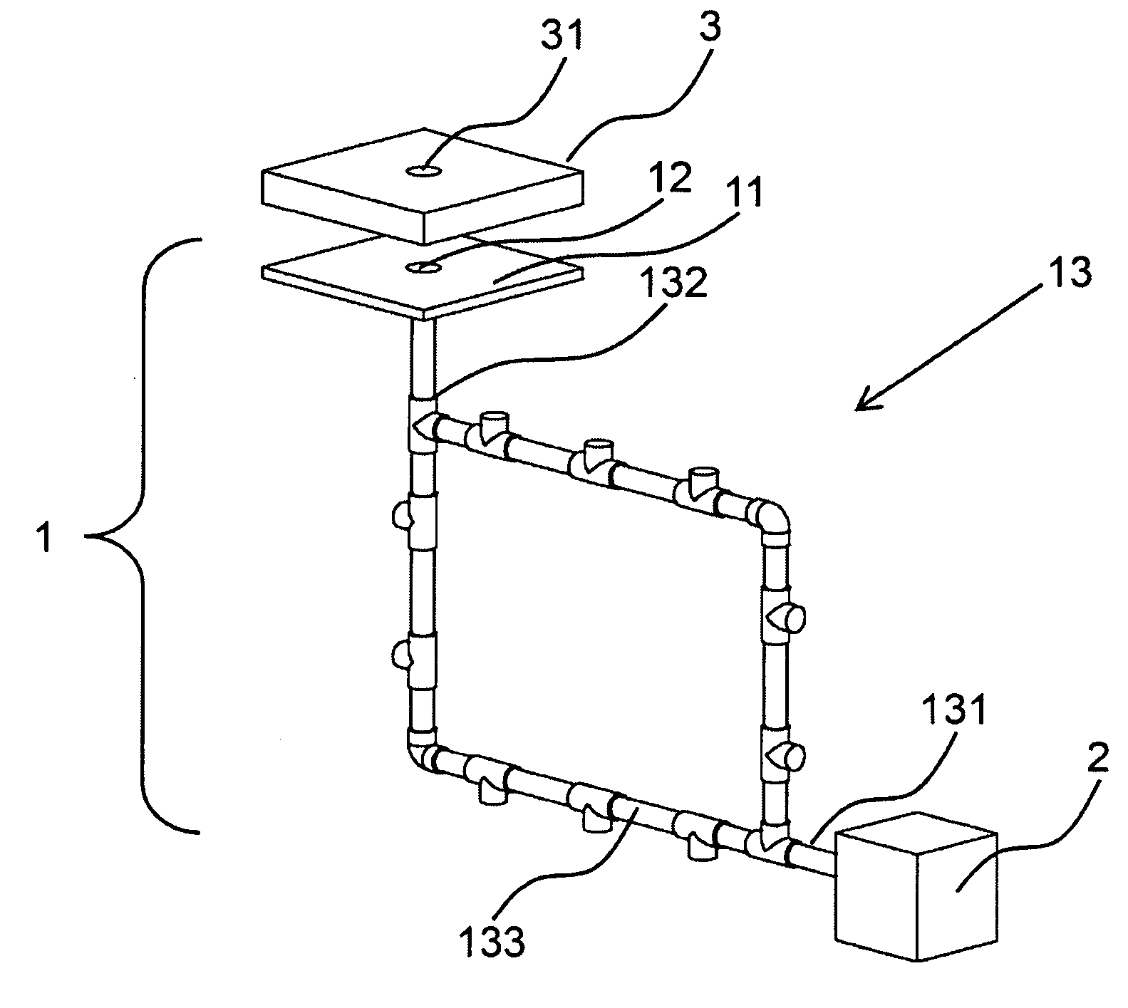
[0025]Please refer to FIG. 1 for a schematic drawing of a gas filling apparatus of the present invention. The gas filling apparatus 1 is connected with an air feed source 2 that is used for filling a gas into at least one storage apparatus 3 for storing a semiconductor element or a reticle. The storage apparatus 3 includes at least one first inlet port 31 to enter the gas into the storage apparatus 3.

[0026]The gas filling apparatus 1 includes at least one base 11, at ...


PUM

PropertyMeasurementUnit
pressureaaaaaaaaaa
flow rateaaaaaaaaaa
light-transparentaaaaaaaaaa

Abstract

This present invention provides a gas filling apparatus for filling a gas into a storage apparatus for storing a semiconductor element or a reticle. The gas filling apparatus is connected with an air feed source, and includes a base, a first inlet port and a set of air feed source route. The storage apparatus is loaded on the base, and the first inlet port which is disposed on the base corresponds with the second inlet port of the storage apparatus. The set of air feed source route includes an entrance part, a supply part and a branch part. The entrance part is connected with the air feed source, and the supply part is connected with the first inlet port. The branch part is a closed loop, which transmits the gas from the entrance part into the supply part.

Description

BACKGROUND OF THE INVENTION[0001]1. Technical Field[0002]The present invention relates to gas filling apparatuses, and more particularly, to a gas filling apparatus for filling a gas into a storage apparatus that is used for storing a semiconductor element or a reticle.[0003]2. Description of Related Art[0004]In the rapidly developing semiconductor technology, optical lithography plays an important role and wherever pattern definition is conducted, optical lithography is requisite. As to the application of optical lithography relating to semiconductors, a designed circuit pattern is used to produce a light-transparent reticle with a particular shape. Basing on the principle of exposure, after a light passes through the reticle to project on a silicon wafer, the circuit pattern formed on the reticle can be exposed onto the silicon wafer. Since any dust (such as particles, powders or an organic matter) can adversely affect the quality of such projected pattern, the reticle used to pro...

Claims


Application Information

Patent Timeline
Patent Type & Authority Applications(United States)
IPC IPC(8): B65B3/04
CPCH01L21/67389H01L21/67359
Inventor WANG, SHENG-HUNGCHIU, MING-LONG
Owner GUDENG EQUIP CO LTD
Why Eureka
Try Eureka