Shaped Selective Thermal Emitter

a selective thermal and wavelength-selective technology, applied in the manufacture of electrode systems, instruments, optical radiation measurement, etc., can solve the problems of structure not being heated and operating in reflective mode, and achieve the effects of low cost reel-to-reel, high efficiency, and simple and cost-effective thin-film processing

Inactive Publication Date: 2009-06-25
MARSHALL ROBERT A
View PDF10 Cites 3 Cited by
  • Summary
  • Abstract
  • Description
  • Claims
  • Application Information

AI Technical Summary

Benefits of technology

[0009]A geometrically-shaped spectrally-shaped thermal emitter is disclosed. The geometry of the emitter is key to many applications and fabrication thereof. A high efficiency light source is disclosed, including a 1D PBG structure deposited on a wire substrate. Use of a wire substrate has several key advantages, including low-cost reel-to-reel processing, spatial integration of the directivity of a PBG light source, and compatibility with existing commodity manufacturing processes, bulbs, sockets, and fixtures. Use of a PBG structure allows shaping of the thermal emission spectra, without the use of hazardous materials. Use of a 1D PBG structure, with or without a cavity, allows the simplicity and cost effectiveness of thin-film processing. A further advantage of a 1D structure is that the center emission wavelength is a function of layer thickness; a gradient in the thickness allows easy profiling of the emission spectra. Modification of color temperature and color rendering are as simple as changing the thickness gradient.
[0010]A TPV generator is disclosed, including a concave PBG emitter. The 1D PBG emitter is simple and cost-effective to manufacture. Also, PBG emitters are directional. This provides a key advantage in providing a lensing effect, optically concentrating the power density on the PV cell.
[0011]An electronically tunable PBG is disclosed. One of the PBG materials is replaced with a piezoelectric material. Application of a voltage changes the resonant wavelength of the structure. Again, the PBG is thermally stimulated to emit light. However, this structure may not be heated and operate in a reflective mode. A pixilated pattern is etched into the PBG on a flexible substrate. This arrangement has the advantage of a single layer of low-cost color-tunable pixels on an emissive flexible display.
[0012]Temperature and strain sensors are also disclosed. Use of high CTE materials shifts the central wavelength as a function of temperature. A strain sensor prefers use of higher modulus materials and must be oriented in the direction of strain. A 3D PBG may be used in this application to sense elongation. A key advantage is these sensors may be deposited on irregular shaped surfaces, such as turbine blades, the sensor is read remotely by sensing the emitted wavelength, is emissive and relatively immune to dirt buildup, and requires no electricity or other wiring.

Problems solved by technology

However, this structure may not be heated and operate in a reflective mode.

Method used


Image

  • Shaped Selective Thermal Emitter
  • Shaped Selective Thermal Emitter
  • Shaped Selective Thermal Emitter

Examples


Embodiment Construction

[0025]Embodiments of the present invention and their advantages are best understood by referring to FIGS. 1 through 10 of the drawings, in which like numerals refer to like parts. The figures are not to scale, especially the apparent thickness of the thin films

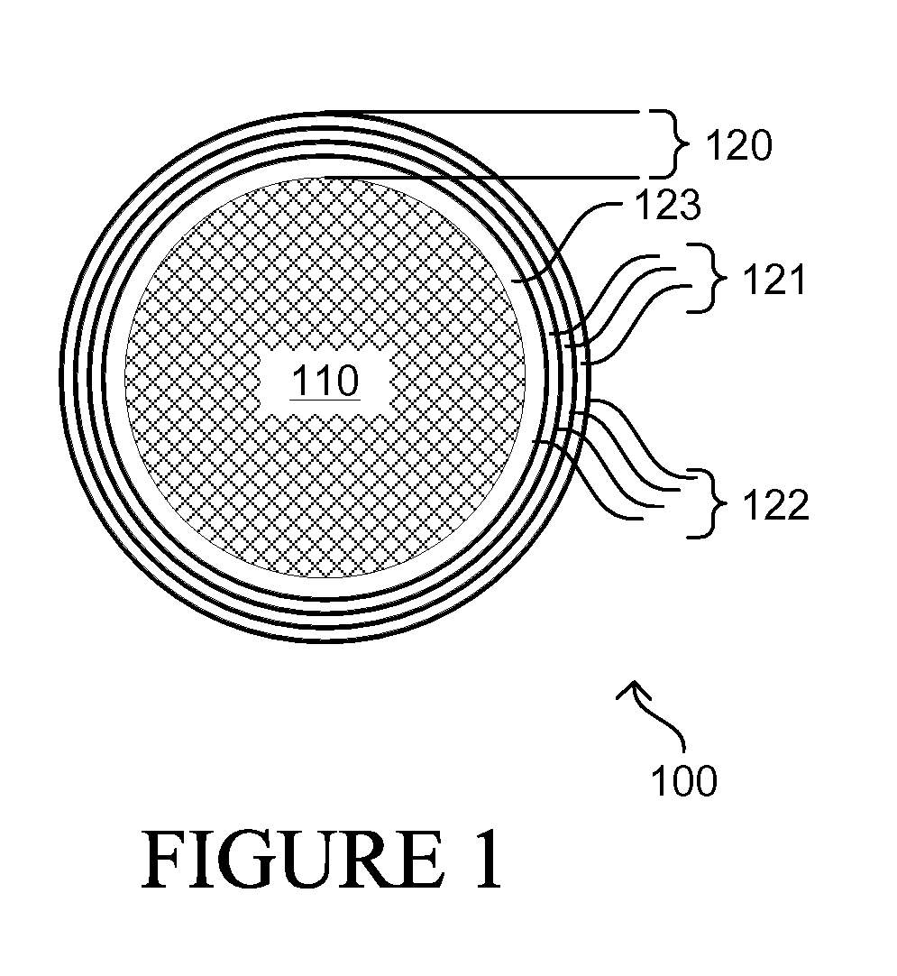
[0026]FIG. 1 is a diagram illustrating a cross section of a filament 100 of a selective thermal emitter. Substrate 110 is a metallic wire or other filamentous substrate capable of resistively heating PBG 120 to emit light. Refractory metals are preferred for their melting point and low diffusion. Alternatively, a non-conductive material may be used for substrate 110 and PBG 120 itself is resistively heated. Use of a wire substrate has several key advantages, including low-cost reel to reel processing, integration of the directivity of a PBG light source, no light intensity non-uniformity or radiative losses from the backside of a planar structure, and compatibility with existing commodity manufacturing processes, bulbs, socket...


PUM


Abstract

A geometrically shaped photonic crystal structure consisting of alternating layers of thin films is heated to emit light. The structure may include index matching layers or a cavity layer to enhance emissions. The layer thicknesses of the structure may be spatially varied to modify the emission spectrum versus emission angle. The self-focusing structure may be fabricated into a convex electrically heated wire filament light bulb, a concave visible thermophotovoltaic emitter, a concentric directional heat exchanger, an electronic display, or a variety of irregularly shaped remotely read temperature or strain sensors.

Description

TECHNICAL FIELD OF THE INVENTION[0001]The invention relates to a geometrically-shaped wavelength-selective thermal emitter, more specifically to a visible light source, thermophotovoltaic emitter, heat exchanger, electronic display, and sensor.BACKGROUND OF THE INVENTION[0002]Today's incandescent lighting is only about 5% efficient, yet enjoys a dominant market share due to a very low cost. A need has arisen for a high efficacy, low cost, non-toxic, fixture compatible, high quality light source. Various technologies have attempted to fill this need, but all have failed in at least one way or another.[0003]ThermoPhotoVoltaic (TPV) electric generation offers the potential to recover vast amounts of waste heat, yet has failed to operate at reasonable efficiency or have a reasonable cost. Also, photonic heat pumps have not yet been commercially realized due to cost / performance issues. A need has arisen for a narrow band thermally driven focused light source.[0004]Electronic displays suf...

Claims


Application Information

Patent Timeline
Patent Type & Authority Applications(United States)
IPC IPC(8): H01K1/30H01J9/02
CPCG01J5/08G01J5/0887H01K1/14H01K1/04G01J5/60
Inventor MARSHALL, ROBERT A.
Owner MARSHALL ROBERT A
Why Eureka
Try Eureka