

Devices and methods for measuring axial distances
a technology of axial distance and measuring device, which is applied in the field of devices and methods for measuring axial distance, can solve the problems of inability to accurately predict the effective lens position, significant challenge in selecting the correct iol power, and patients who will unfortunately require additional corrective lenses
- Summary
- Abstract
- Description
- Claims
- Application Information
AI Technical Summary
Benefits of technology
Problems solved by technology
Method used
Image

Examples
example 1
Method of Predicting Effective Lens Position (ELP)
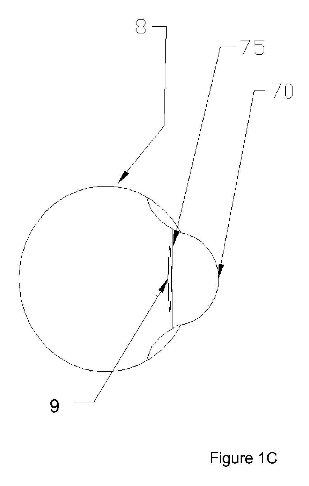
[0061]This protocol provides an exemplary method of predicting ELP using a measurement device including a relay lens system. See, e.g., FIG. 8. In this example, the distance between the apex of the cornea and the pupil is measured in an aphakic eye.
[0062]Align the visual axis of the camera with the eye's optical axis. Position the eye within the operating range of the device. In general, the operating range will be within two focal lengths of the first lens. Place the camera at a starting position far enough away from the eye such that no ocular structure would be in focus. Keeping the relay lens system stationary relative to the eye, move the camera toward the eye while recording the captured images therefrom. (This operation could, of course, be equally effective performed in reverse. In other words, place the camera at a starting position close enough to the eye such that no ocular structure would be in focus and then move the cam...
example 2
Exemplary Device
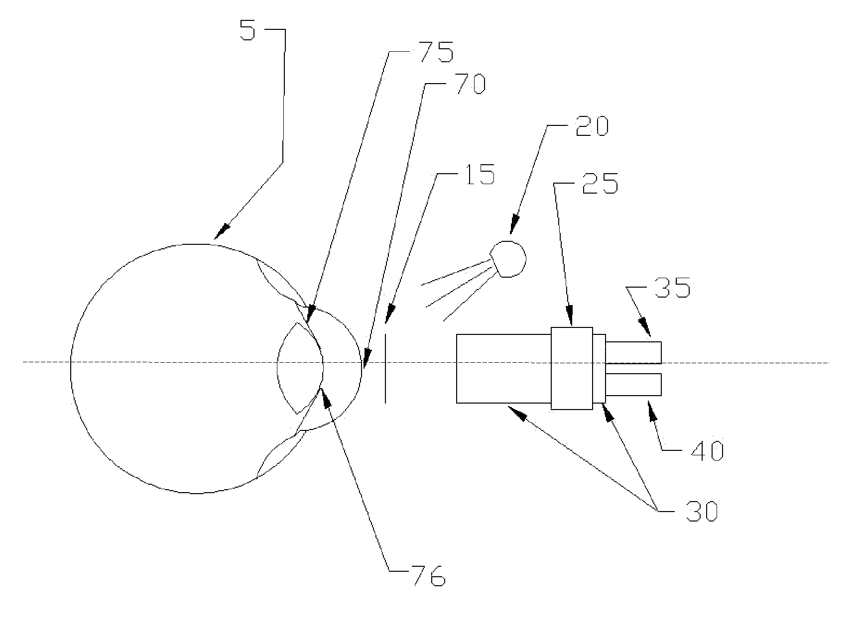
[0065]An exemplary device was constructed as depicted in FIG. 6. The camera (25) was a Watec 903(k) fitted with a Tamron 25 mm c-mount lens, with 10 mm of spacer rings between them. The camera was mounted onto Velmex UniSlide (30). A Newport Optics LTA-HS motorized actuator served as both actuator (35) and position detector (40).
[0066]The relay lens system was constructed with two Edmund Optics 25 mm diameter lenses, 100 mm focal length achromats, spaced 200 mm apart.
[0067]The beam splitter (60) was a Tower Optical Corp. Hot Mirror. The light source (45) was an Exalos 840 nm SLED mounted in a Thor Labs collimator.
[0068]Images were digitized through an Imperx VCE frame grabber operating in a Sony VAIO laptop PC.
example 3
Measuring an Axial Distance In Vivo
[0069]The device of Example 2 was positioned in front of a human eye such that the focus plane (85) was deep enough into the eye that neither the pupil nor the corneal-apex-created virtual image were in focus to the camera. The actuator / detector moved the camera away from the eye at 4 mm per second. The computer acquired images at 30 frames per second. The camera movement continued until the best focus of the corneal apex and the pupil edge came and went. Then the movement and image acquisition were terminated.
[0070]The images were then analyzed using MatLab. The edge of the pupil was examined for contrast, and the results were plotted. See FIG. 11. The virtual image of the light source was examined for size, and the results were plotted. See FIG. 12. The corneal curvature was determined from the subject's eye prescription. The plot of the pupil edge was examined, and the point of best focus was determined. This point indicated the image frame of p...
PUM
 Abstract
Description
Claims
Application Information