
Intake controller for internal combustion engine

Inactive Publication Date: 2009-06-25
DENSO CORP
View PDF14 Cites 24 Cited by
  • Summary
  • Abstract
  • Description
  • Claims
  • Application Information

AI Technical Summary

Benefits of technology

[0013]The present invention is made in view of the foregoing problem and an object of the present invention is to provide an intake controller for an internal combustion engine which can accurately detect a valve position regardless of presence / absence of power supply to a motor. Another object of the present invention is to provide an intake controller which can prevent erroneous learning of a reference position on control. Another object of the present invention is to provide an intake controller which can prevent that a normal sensor is diagnosed in error to be abnormal (defective).
[0014]According to an aspect of the present invention, an intake controller for an internal combustion engine is constructed so that at the time of supplying the power to a motor, a taking-in timing of output of the motor is set close to an integral multiple of a power supply start timing to the motor. The output of the sensor is taken only during an OFF-period of power supply in a pulse signal generation period. In consequence, since the valve position is detected from the sensor output which is taken in during the OFF-period of the power supply where the output variation of the sensor including a non-contact magnetic detection element is small, the valve position can be accurately detected regardless of presence / absence of the power supply to the motor.
[0016]In consequence, even in a case that the power is continuously supplied to the motor even after a valve is driven to a reference position whereby the magnetic field in the circumference of the sensor is changed to vary the output of the sensor, the sensor output taken in during the ON-period is ignored. For example, the sensor output is not used for reference position learning or sensor failure diagnosis. Since the position of the valve is detected from the sensor output taken in during the OFF-period of the power supply, the valve position can be accurately detected regardless of presence / absence of the power supply to the motor.

Problems solved by technology

In such an electronic throttle controller, the fully closed position learning value of the throttle position sensor may be shifted to a position more closed than an actual fully closed position due to an individual component difference or an assembly error.
Therefore, the drive duty ratio of the motor is rapidly increased to the maximum duty ratio (duty ratio of 100%), possibly damaging wires of the motor with heat.
Therefore, it is difficult to maintain the valve body of SCV or TGV in a state of the fully closed position.
Therefore, it is difficult to maintain the valve body of SCV or TGV in a state of the fully open position.
Therefore, a detection accuracy of the valve position sensor deteriorates.
Therefore, there is the possibility that it is detected in error (diagnosed in error) that the valve position sensor is abnormal (defective).

Method used


Image

  • Intake controller for internal combustion engine
  • Intake controller for internal combustion engine
  • Intake controller for internal combustion engine

Examples


first embodiment

Advantages of First Embodiment

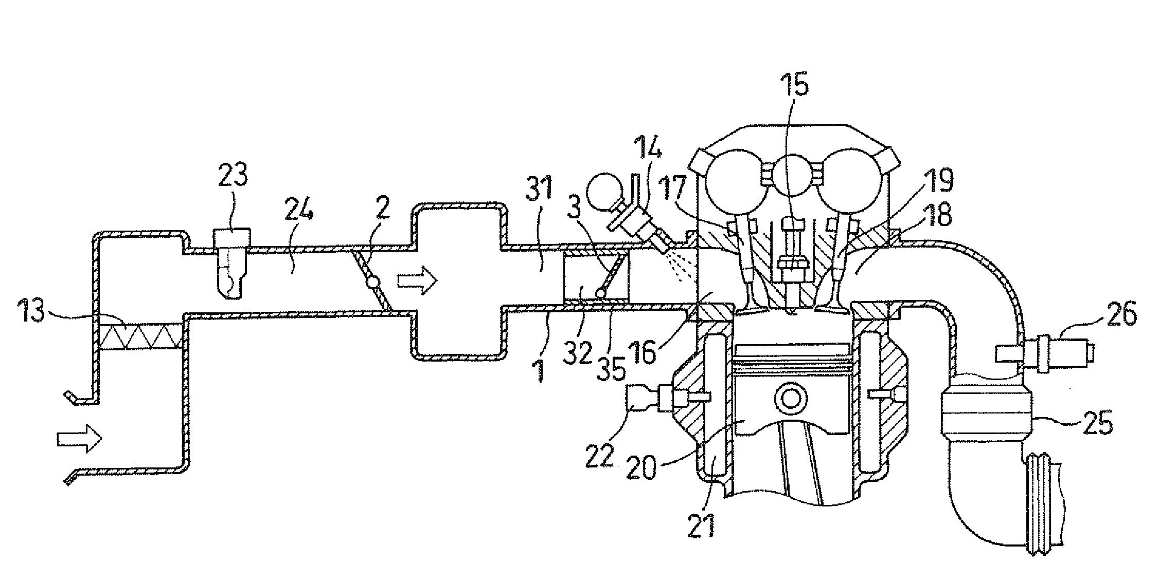
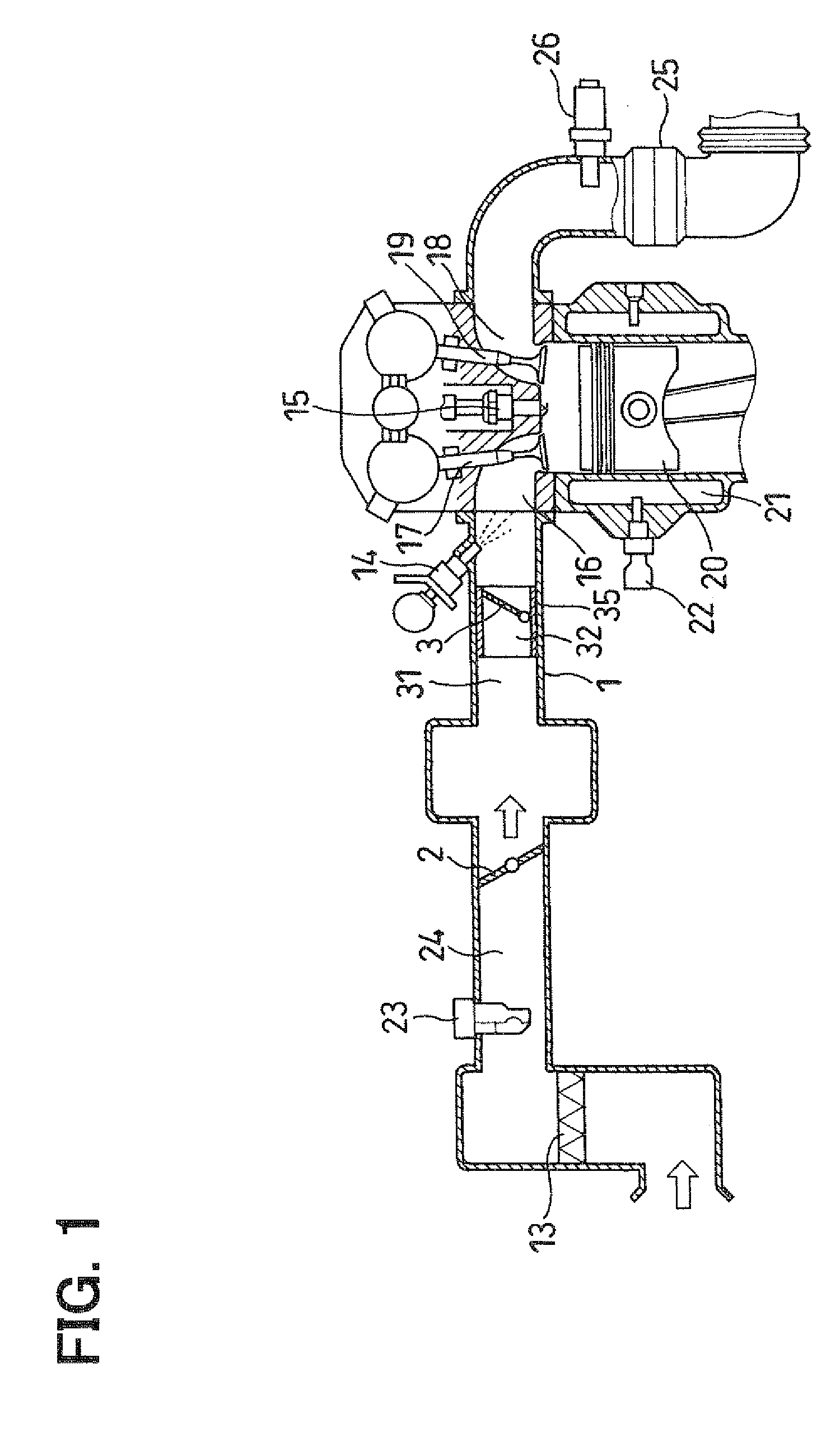
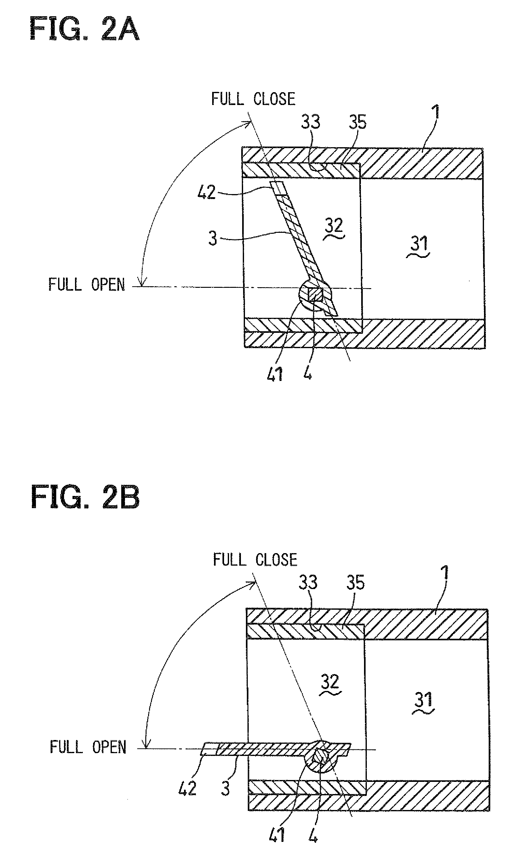
[0094]As described above, in the intake controller (intake vortex generating device) for the internal combustion engine in the present embodiment, cantilever type valves are adopted as the plurality of the intake flow control valves 3. The ECU 6, for coping with the intake pulsation torque in the first and second intake passages 31 and 32, supplies the motor application voltage or the motor drive current by which the plurality of the intake flow control valves 3 can be retained in a state of bumping the plurality of the intake flow control valves 3 against the limit position of the possible operating range (fully closed position or fully open position), to the coil of the second motor 12. At this time, as shown in FIGS. 10A and 10B, the AD taking-in timing of the output signal of the valve position sensor 7 is set to the integral multiple of the power supply start timing to the second motor 12 in the PWM period of the PWM signal provided to the H-bridge...

second embodiment

[0097]FIG. 13 shows a second embodiment of the present embodiment and is a flow chart showing a reference position learning process. The control routine in FIG. 13 is executed when the determination result in step S36 is YES.

[0098]When this determination result in step S36 is YES, it is determined whether or not there occurs the sampling period (AD taking-in timing of the output signal of the valve position sensor 7) for A / D conversion of the output signal of the valve position sensor 7 in step S51. When the determination result is NO, the determination process in step S51 is repeated. When this determination result in step S51 is YES, the output signal of the valve position sensor 7 is taken in the A / D conversion circuit 48 in step S52. In step S53, the actual valve position of TCV is detected (calculated) based upon the A / D conversion value of the output signal of the valve position sensor 7 which is converted from an analogue signal to a digital signal at the A / D conversion circu...


PUM


Abstract

At the time of supplying power to a coil of a motor in an intake vortex generating device, an AD taking-in timing of an output signal of a valve position sensor is synchronized with a power supply start timing to the motor in the PWM period of the PWM signal applied to an H-bridge circuit. The output signal of the valve position sensor is taken in only during an OFF-period of power supply in the PWM period. An actual valve position of TCV is detected from an A / D conversion value of the output of the valve position sensor taken in during an OFF-period of the power supply in the PWM period where the output variation of the valve position sensor is small. Therefore, an actual valve position of TCV can be accurately detected regardless of presence / absence of the power supply to the coil of the motor.

Description

CROSS-REFERENCE TO RELATED APPLICATION[0001]This application is based on Japanese Patent Application No. 2007-329572 filed on Dec. 21, 2007, the disclosure of which is incorporated herein by reference.FIELD OF THE INVENTION[0002]The present invention relates to an intake controller for an internal combustion engine provided with an intake passage-opening / closing device for opening / closing an intake passage communicated with a combustion chamber in the internal combustion engine. In particular, the present invention relates to an intake controller for an internal combustion engine provided with an intake vortex generating device to generate an intake vortex in a combustion chamber for the internal combustion engine.BACKGROUND OF THE INVENTION[0003]Conventionally, an intake vortex generating device is known as an intake controller for an internal combustion engine. This intake vortex generating device throttles a passage cross section area of an intake passage communicated with a comb...

Claims


Application Information

Patent Timeline
IPC IPC(8): F02D41/18
CPCF02B31/08F02D9/02F02D9/1025F02D9/1065Y02T10/42F02D2041/2027F02D2250/14F02D2250/16Y02T10/146F02D2041/0015Y02T10/12Y02T10/40
Inventor UDA, TOSHIAKI
Owner DENSO CORP
Learn More